Being on a budget doesn’t necessarily mean you can’t take on advanced DIY projects. If you're looking for a small, affordable, and convenient WiFi module to scale up your IoT projects, the ESP-01 module is a great choice. However, integrating such a module with a lightweight protocol like MQTT can be tricky, especially if you're new to IoT development.
Programming the ESP-01 board alone can be challenging compared to other modules of the ESP8266 series. But let's go over the basics of all the hardware and software setup you need to start using the module as well as how to set up MQTT in a simple and procedural way.
Getting to Know the Board
ESP8266 ESP-01 is a small and compact WiFi module that comes with an ESP8266EX chip, which is a highly integrated SoC designed for IoT applications.

The module includes a single-chip wireless microcontroller with a TCP/IP protocol stack and is capable of connecting to a wireless network or acting as an access point. The ESP-01 module also features a 2x4 pin header that provides access to its GPIO pins, power and ground, and UART interface.
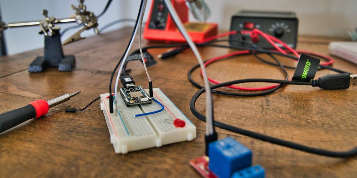
Setting Up the Hardware
The module is not breadboard friendly at all. For convenience, you can buy a pre-built extension board or just go the old-fashion way—using jumper wires and a breadboard.
There is a dedicated programmer, the ESP8266 Serial Module Board, that can ease your programming experience. If you prefer to go this route, DIYHOBI has a handy tutorial on how to flash a program into the ESP-01 module using a programmer (including the USB to TTL CH340G Converter Module Adapter).
But, you can still program the module using an Arduino board. Look at the circuit diagram below for reference.

While it may look tempting, we generally don't recommend connecting the module directly to the Arduino's 3.3v pin since it requires more current than the pin provides. Instead, connect the Arduino 5V to a 3.3V voltage regulator like LM1117/LD117, then power the WiFi module from the regulator.
Don’t connect the VCC and CH_PD pins of the ESP to the 5V pin of the Arduino. Connecting the module to 5V power can damage it.
All the capacitors are 10uF and the resistor is a 1K resistor.
Software Requirements
The ESP-01 module is commonly used with the Arduino platform. As such, setting up the software is pretty simple, especially if you are familiar with Arduino C. However, if you are more familiar with Raspberry, there are plenty of Raspberry Pi IoT projects you can try.
These are the basic requirements:
- An MQTT broker or server (such as Mosquitto or CloudMQTT).
- An Arduino IDE with the ESP8266 core library.
- The PubSubClient library for Arduino.
You have to remember that having your own MQTT server locally gives you flexibility within your projects.
Installing the Necessary Libraries
First, download and install the Arduino IDE on your computer. Once installed, open the Arduino IDE, and go to File > Preferences.

In the Additional Boards Manager URLs field, enter the following URL:
http://arduino.esp8266.com/stable/package_esp8266com_index.json
Click OK to close the Preferences window.

Next, go to Tools > Board > Boards Manager.
Then search for esp8266 and install the esp8266 board package—this includes all the necessary libraries for the ESP-01 module.

To install the PubSubClient library, go to Sketch > Include Library > Manage Libraries.

Search for PubSubClient and click on the library to install it.

Once you have all the necessary libraries installed, you can start programming the ESP-01 module. One thing to note though, is you can use the Wifi.h which is included in the library, or download the ESPWifi.h library and include it in your sketch.
Establishing a Connection Between ESP-01 and MQTT Broker
An MQTT broker is a server that acts as an intermediary between MQTT clients. It allows clients to send and receive messages to and from each other through a publish-subscribe model.
To connect your ESP-01 module to an MQTT broker, you will need to specify the broker's IP address and port number in your code. You will also need to provide a unique client ID that identifies your ESP-01 module to the broker.
First, include the necessary libraries at the top of your sketch
        #include <ESP8266WiFi.h>
#include <PubSubClient.h>
Next, define the WiFi and MQTT connection details.
        const char* ssid = "YOUR_SSID";
const char* password = "YOUR_PASSWORD";
const char* mqtt_server = "YOUR_MQTT_SERVER";
Don’t forget to replace the placeholders with your own WiFi and MQTT connection details.
After that, create a WiFi client and connect to your local WiFi network:
        WiFiClient espClient;
void setup_wifi() {
  delay(10);
  WiFi.begin(ssid, password);
  while (WiFi.status() != WL_CONNECTED) {
    delay(500);
  }
}
This function should be called in the setup() function of your sketch.
Next, you'll need to create an MQTT client and connect to your MQTT broker:
        PubSubClient client(espClient);
void reconnect() {
  while (!client.connected()) {
    if (client.connect("ESP01", mqtt_user, mqtt_password)) {
      // Subscribe to a topic
      client.subscribe("test/topic");
    } else {
      delay(5000);
    }
  }
}
Once you have connected to your MQTT broker, you can start publishing and subscribing to topics.
Publishing Data From ESP-01 to MQTT Broker
Now that you have successfully connected your ESP01 module to the MQTT broker, let's look at how you can publish data from the ESP-01 to the broker.
To publish data, use the client.publish() function to publish a message to the inTopic topic.
client.publish("inTopic", "Hello from ESP-01");
This will publish the message "Hello from ESP-01" to the inTopic topic.
You can also publish sensor data from the ESP-01 to the broker. For example, if you have a temperature sensor connected to your ESP-01, you can publish the temperature data to the broker as shown below.
        float temperature = 25.5;
String temperatureString = String(temperature);
char temperatureChar[5];
temperatureString.toCharArray(temperatureChar, 5);
client.publish("Temp", temperatureChar);
This will publish the temperature data to the Temp topic.
Data can be published in a loop or at regular intervals, depending on your project's requirements. Make sure that you're not flooding the broker with too much data and that you're publishing at a reasonable interval.
Subscribing to MQTT Topics and Receiving Data on ESP-01
To subscribe to a topic, use the client.subscribe() function. For our case below, the client subscribes to the outTopic topic.
client.subscribe("outTopic");
Once you have subscribed to a topic, you can receive messages published to that topic using the client.loop() function in the loop() function in the sketch below:
        void loop() {
  if (!client.connected()) {
    reconnect();
  }
  client.loop();
}
This will continuously check for new messages and execute the callback function when a new message has been received.
To handle received messages, define a callback function like the one shown below:
        void callback(char* topic, byte* payload, unsigned int length) {
  // Print the received message
  Serial.print("Message received on topic: ");
  Serial.print(topic);
  Serial.print(". Message: ");
  for (int i=0;i<length;i++) {
    Serial.print((char)payload[i]);
  }
  Serial.println();
}
This function will be called when a new message is received on the subscribed topic. It will print the received message to the Serial Monitor.
Using QoS (Quality of Service) Levels and Security Features
One of the most important techniques used in handling requests is using QoS (Quality of Service) levels for your MQTT messages. QoS levels define how the broker and subscribers should handle your messages. There are three levels of QoS: 0, 1, and 2.
QoS level 0 is the least reliable, as messages are sent only once and are not guaranteed to be delivered to the subscriber. QoS level 1 is more reliable, as messages are sent at least once and are guaranteed to be delivered to the subscriber at least once. QoS level 2 is the most reliable, as messages are sent exactly once and are guaranteed to be delivered to the subscriber exactly once. How your devices communicate falls in line with other common Internet of Things (IoT) security issues and fixes you want to stay on top of.
To use QoS levels, you can specify the desired level when publishing messages using the client.publish() function:
client.publish("topic", "Hello, world!", 1);
This will publish the message Hello, world! to the topic topic with QoS level 1.
Another advanced technique is using Last Will and Testament (LWT) messages. LWT messages are messages that are sent by the broker when a client unexpectedly disconnects. We believe this is important for detecting offline devices or for triggering actions when a device disconnects.
To use LWT messages, you can specify the LWT message when connecting to the broker using the client.setWill() function:
client.setWill("status", "offline", 1, true);
This will set the LWT message to offline on the status topic with QoS level 1 and the retain flag set to true.
Prep Up for Your Next IoT Project
The ESP-01 module is an affordable and compact solution for IoT projects, and using it with MQTT can take your project to the next level. Although the initial setup can be daunting, the benefits of MQTT, such as lightweight communication and high scalability, make it a worthwhile investment.