There are so many electronic gadgets and appliances available these days, designed for a wide range of purposes. The common factor is that they are all powered by electricity. The latter comes in two forms: direct current (DC) and alternating current (AC). The ability to measure these currents is pivotal to identifying issues in an electronic circuit or appliance. We'll show you how to measure current with a digital multimeter.
Understanding Current in Simple Terms
Electric current is simple to understand with the help of the analogy of a water flow system inside a building, where water is pumped from the ground to the overhead tank, and the water flows back to the ground through the pipes. An electrical system is quite similar: electrons are moved through the circuit instead of water. Other components of the electrical system can also be visualized using the same model.

Similarities Between Both the Systems
The positive terminal of the power source (e.g., a battery) is similar to the level of the overhead tank and the negative terminal to the ground level. This potential difference between both terminals is called voltage and is measured in volts, abbreviated as "V".
The higher the tank, the greater the pressure of the water. Similarly, the higher the potential difference between the battery terminals, the greater the electrical pressure (voltage). It is this voltage that drives the current through the circuit. The greater the voltage, the more current circulates in the circuit. Current is measured in amperes, abbreviated as "A".
Voltage is measured across the terminals of the power source (just as measuring the height of the overhead tank). Current is measured inside the circuit (similar to measuring water with a flow meter). Current is measured using an ammeter, which is included in a multimeter.

Current Measuring Features of a Multimeter
A digital multimeter has an LCD, a rotary selector, and ports to connect the probe wires. It is usually powered by a 9V battery. Two probes need to be connected to the respective ports depending upon the type of measurement. The black probe is connected to COM (short for "common"), connected to ground. As for the red probe, for low currents the mA port is used; for high currents, the 10A port is used.
For 10A, the warning on our multimeter shows "UNFUSED 10A MAX For 10 SECONDS MAX" (yours may differ). This means the multimeter can withstand a sustained flow of 10A for a maximum of 10 seconds before the wires inside get hot enough and will possibly melt.

Measuring the Current Draw of DC Electronic Components
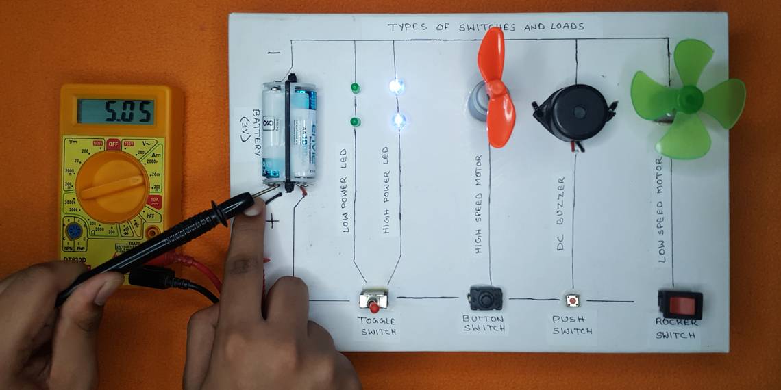
A test board is set up with a battery pack, LEDs, buzzer, a low-speed motor and a high-speed motor. Using the switches, each of these will be powered on in turn to measure the current.

This is the circuit diagram of the test board. Current can be measured by connecting the multimeter in series at any part of the circuit.

For convenience, the probes are connected closer to the battery. This will help measure current when any or all of the switches are turned on. The black probe is connected to the negative terminal of the battery and the red probe is connected to the other wire to form a series circuit.
Before you proceed to measure the current with a multimeter, it is wise to have a rough estimate of the current that will be measured. This is required because the red probe needs to be connected to the correct port of the multimeter.
To estimate, look for the specifications of the component. For example, if a 5V DC motor has a 0.5W power rating:
- Current = Power / Voltage
- Current = 0.5 / 5
- Current = 0.1A = 100mA
Now that you have an approximate value of the current, connect the lead to the regular mA port and set the rotary switch of the multimeter to 200mA.
In practice, though, it is quicker to start with a higher value on the multimeter rotary dial and move to lower values for precision. If you do not have access to the specification of the electronic component, this is what you should do.
LEDs are known to consume low power, so the multimeter is set to measure current in milliamps (mA). Upon measuring, the two bright LEDs are shown to be consuming only 7.43mA.

Similarly, buzzers do not consume much power. It is even more frugal at 2.04mA.

Measuring the current of the low-speed motor shows 0.37A (370mA). Note that the multimeter port and rotary dial have been changed to 10A.

The high-speed motor, as expected, is consuming even more at 0.53A (530mA).

Measuring AC Current
Unlike direct current, alternating current (AC) does not find many applications in low-voltage electronics. It is the reason many multimeters do not feature an AC ammeter. But for those that do, measuring AC is a similar process as DC; the rotary dial needs to be set to AC, though.
Measuring Current in AC Appliances
The primary benefit of AC is the minimal power loss during transmission across long distances. AC voltage is stepped down using transformers and fed to the appliances. Smaller appliances convert the current to DC and use it (examples include phone chargers and laptops). Larger appliances use AC directly (examples include water heaters and motors).
The voltage that is fed to these appliances varies between 120V and 230V depending upon the standards adopted by different countries. It is important to note that these voltages are high enough to cause injury or even put human life at risk if handled without proper precautions. Since current is measured inside a circuit, it is strongly advisable NOT to use a multimeter when measuring high-voltage AC current.
What you can do is to use a clamp meter to measure AC currents. The meter uses the electromagnetic field of AC current to measure current, and does not need to be in contact with the wire, so it is safe. The clamp needs to be placed around the wire and the reading will be displayed; it can measure currents as high as 1000A.

There is one problem with clamp meters, though. The clamp should be placed around only one wire to obtain a reading. But, power cords of appliances are usually a bunch of three wires (live, neutral, and earth). So, a wall socket ammeter would be ideal to measure appliance currents.

Measuring and Monitoring Current in 5 Volt Gadgets
Many modern gadgets are powered by 5V USB adapters and power banks. It is useful to measure the current to understand the vitals, for example to not overcharge the batteries during charging. This can be done by using a regular multimeter: you can use a USB extension cable, remove the sleeve, cut the positive wire, then connect its ends to the multimeter’s probes and measure the current. However, that's a cumbersome solution.
What is easier is to use a USB multimeter that’s specifically designed to measure the two important parameters, voltage and current. Just connect it in line and the readouts will be displayed intermittently.

The meter is simple, yet again a very useful gadget. Say you buy a new iPhone Pro Max 14 without the official Apple charger. You buy a third-party charger separately, kept your trust in the stickers, and plug it in. What happens next depends on how lucky you are. The possible results range between a beep and a kaboom.
A wiser choice is to check the adapter before plugging it into your expensive phone. If there is a problem, the worst that could happen is that the inexpensive USB meter would blow up rather than your $1000+ phone.

You can also use the USB meter to check computer ports and make sure the voltage is right and enough amperage is delivered to drive the peripherals such as a USB hard drive.

The USB meter can be used for continuous monitoring too. Phones that do not come with LED charging indicators need to be checked by switching on the screen, to see if the charging is complete. A USB ammeter shows the continuous current flowing through the circuit. A high current reading means the phone is still charging; a low one means charging is complete.

Single-board computers like the Raspberry Pi are also powered by 5V USB. The performance of the Pi is directly affected by the quality of the power supply. You may notice a flashing red light on the Pi board, which indicates an inadequate power supply. With the USB multimeter, you can monitor the voltage and the current going to the Pi, correct the power supply, and extract the best performance.

Understanding and Measuring Current Is Easy
You now know how to measure current with a digital multimeter, and also a clamp meter or USB multimeter. Along with measuring current, a multimeter can be used to measure voltage, resistance, and many other electrical parameters. Learning to use one is the gateway to understanding the world of electronics.