Getting into DIY Arduino robotics can be intimidating if you've never coded before. No matter how grand your ideas are if you can't program your microcontroller your robot isn't going to do much.
Luckily, there are ways to program your Arduino without writing a single line of code. Today we are looking at basic robotics using Xod, an open source visual programming node-based Arduino compatible IDE.
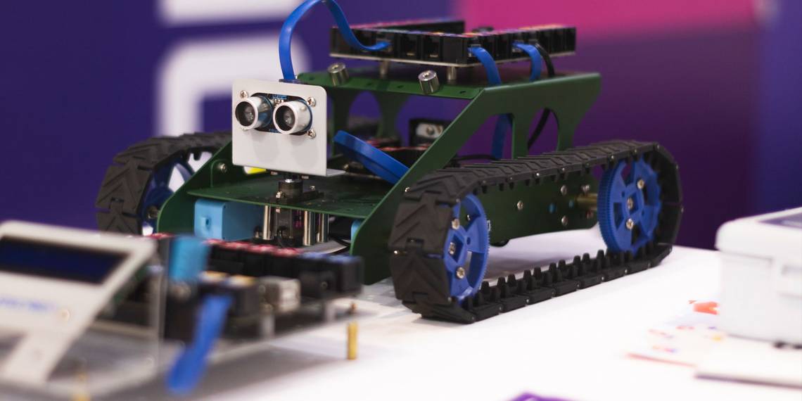
The Code-Free Robot
Today's project uses some standard hobby robotics components to create a prototype of a distance sensing robot arm. The combination of a servo and an ultrasonic distance sensor are common in hobby robotics, and you will be adding an LCD screen.
The finished project will log distance values on the LCD screen, and move the servo arm in proportion to the distance detected by the range detector.
With a little imagination, this is a robot arm which tries to grab you if you get too close. Spooky!
Hardware Requirements

You Will Need:
- Arduino compatible board (this project uses an Uno)
- 16x2 LCD screen
- HC-SR04 ultrasonic distance sensor
- Hobby servo
- 10k potentiometer
- 220 ohm resistor
- 5v power supply
- Breadboard and hookup wires
There are quite a few components required for this project, but any good Arduino starter kit should have everything you need. I found everything I needed in the Elegoo Uno R3 starter kit. Alternatively, every component listed above is super cheap and available at all good hobby electronic retailers.
Setting Up the LCD Screen

Add your LCD screen, 10k potentiometer, and 220 ohm resistor to the breadboard according to the above Fritzing diagram.
Setting up an LCD can be pretty intimidating the first time you do it, but keep referring to the diagram, and you'll get it! To make it simpler, I've set the LCD and Arduino pins to be exactly the same as in the official Arduino LCD tutorial so refer to that too if you get stuck.
Adding the Servo and Ultrasonic Sensor
Now add your HC-SR04 ultrasonic sensor to the breadboard. Connect the VCC and GND pins to the 5v and ground rails of the breadboard. Connect the Trig pin to Arduino pin 7, and the Echo pin to 8.

Next, attach your servo. The wiring colors can vary here, but as a general rule red connects to the 5v pin, and brown or black attach to the GND pin. The data line, which is usually yellow or orange, connects to pin 10.

Finally, connect the ground rail of the breadboard to one of the Arduino's GND pins. That's it! You are all set up.
Downloading the Xod IDE

Head to Xod.io and download the free Xod IDE. It's available for Windows, Mac, and Linux. There is also a browser-based version, but since you cannot use it to upload Arduino sketches, it will not work for this project.
Download: Xod IDE for Windows, Mac, and Linux
Blink With Xod
When you open Xod for the first time, you'll see the tutorial project; alternatively you can open it under the Help menu. Unfold the welcome-to-Xod collection in the project browser on the left, and select 101-upload.

This node setup is for testing if code uploads successfully to the Arduino. It functions the same way as a Blink sketch in the Arduino IDE. The clock node creates a signal every second. This connects to the flip-flop node, which switches back and forth between true and false every time it receives the signal. The output of the flip-flop connects to the led node, turning it off and on.
Click on the led node, and you'll see the Inspector pane changes to show its parameters. Change the Port to 13 as shown above, the pin with an onboard LED on an Arduino. Notice that Xod automatically turns 13 into D13. You don't need to type the D yourself, but it makes no difference to this tutorial if you do!
To test if it works attach your Arduino via USB, head to Deploy > Upload to Arduino and select the correct board type and COM port.

If you see the Arduino LED flashing, you are good to go! If not, check your board and port number and test again before continuing.
Programming the LCD
Usually, we'd be getting into the long process of coding now, but since we are using Xod, we won't be writing any. In the project browser, select text-lcd-16x2---you'll find it under xod/common-hardware. Drag it into your program, and use the Inspector to set it up with the pins as shown.

L1 is the first line of the LCD, and L2 is the second, for now we've hardcoded "Hello World" to check everything is working. Deploy your program to the Arduino to see it working. If your text is hard to see, try turning the 10k potentiometer to adjust the LCD contrast.

Now to set up the distance sensor, and get it talking to the LCD screen.
Distance Sensing
Drag the hc-sr04-ultrasonic-range node into your project, and set the TRIG and ECHO pins to 7 and 8 to match how you set it up earlier.

You'll find the concat node under xod/core in the project browser. Drag it between your ultrasonic range sensor node, and the LCD node. You'll use this to concatenate (which is a fancy word for combine) the readout of the range sensor with some text of your own.
This image shows what is going on. The Dm output from the range sensor node is plugged into IN2, and you can see the Inspector marks it as linked. Type "Distance: " into the IN1 box. Now, link the output of the concat node to L1 of the LCD node.

Save and deploy the modified program. The top line of the LCD now shows the reading from the range sensor!

Servo Setup
Getting the servo going requires three parts, so let's go through them one by one. Start by dragging a map-clip node from xod/math into your program. This node takes information from the Dm output of the range sensor node and maps it to values the servo understands.

Smin and Smax represent the minimum and maximum range to activate the servo, in this case between 5 and 20cm. These values are mapped to Tmin and Tmax, which are set to 0 and 1 as the minimum and maximum servo position.

The fade node under xod/core takes the output value of the map-clip node and smooths it at a defined rate. This prevents any unwanted jerky servo movement. A rate of 2 is a good balance, but you can experiment with different values here to make the servo react faster and slower.

Finally, the servo node, which you'll find under xod-dev/servo, takes the output value from the fade node. Change the port to 10. You can leave UPD on Continously as we want our servo to be continuously updating based on the range sensor.

Save your script and deploy it to the Arduino board. Your prototype robot arm is finished!
Testing It Out

Now, when you put something close to the range sensor, the LCD logs the distance, and the servo moves proportionately to the distance detected. All of this without any code at all.

The full node tree shows just how simple it is to create complex programs in Xod. If you are having any problems, check both your circuit and each node carefully for errors.
The No-Code Arduino Robot
Xod allows anyone to program Arduino boards, regardless of coding knowledge. Xod even works with the Blynk DIY IoT app, making a complete code free DIY smart home a real possibility.
Even with tools like Xod, learning to code is important for DIY projects. Luckily, you can learn code on your smartphone to pick up the basics!