The Internet of Things has vast DIY potential. With enough know-how and a few cheap components, you could build a complex system of connected devices.
Sometimes, however, you want something simple. No bells or whistles, just a button that performs a single task. You might already be familiar with something like this if you've ever used an Amazon Dash button to reorder everyday household items.
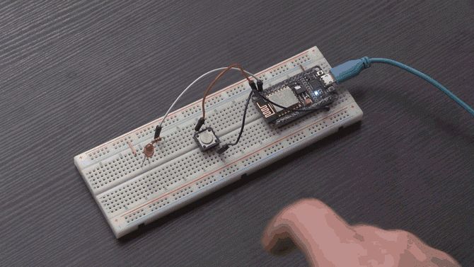
Today we will make a Wi-Fi enabled button using a NodeMCU, and program it to use IFTTT to do… well, anything! Written instructions following the video, if you prefer.
What You'll Need
You will need:
- 1 x NodeMCU (ESP8266) board, available for $2-3 on AliExpress
- 1 x Pushbutton
- 1 x LED (optional)
- 1 x 220 Ohm resistor (optional)
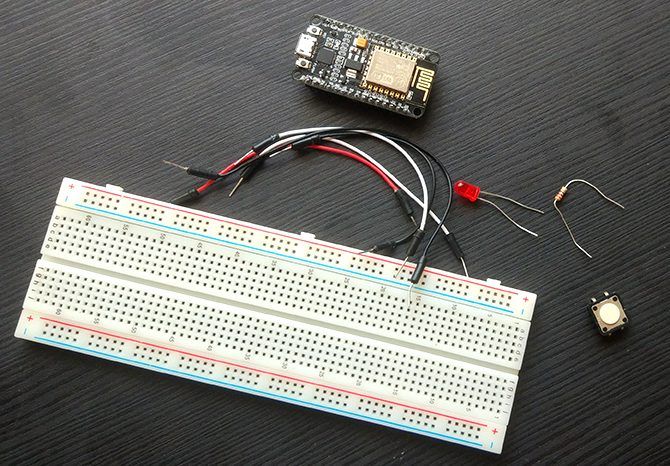
- Breadboard and hookup wires
- Micro USB for programming
- Computer with the Arduino IDE installed
Apart from the NodeMCU, you should be able to find most of these parts in any Arduino starter kit. This tutorial will assume you are using the optional LED and resistor, but they are not essential.
Step 1: Setting Up the Circuit
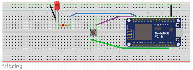
The hardware setup is very simple for this project. Set up your board according to this diagram.
The purple wire attaches pin D0 to one side of the button. The green wire connects the other side of the button to the RST pin. The blue wire runs from pin D1 to the resistor and LED. The negative leg of the LED attaches to the GND pin of the NodeMCU.
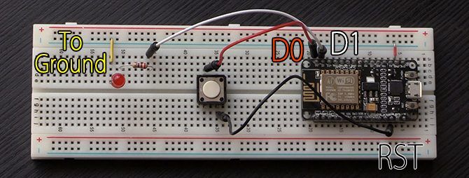
When the breadboard is set up it should look something like this:
If you are wondering how I've got my LED going to the ground pin using just those tiny bits of cable, our quick breadboard crash course should help clear it up! Check your setup and attach your NodeMCU to the computer via USB.
Step 2: Setting Up the IDE
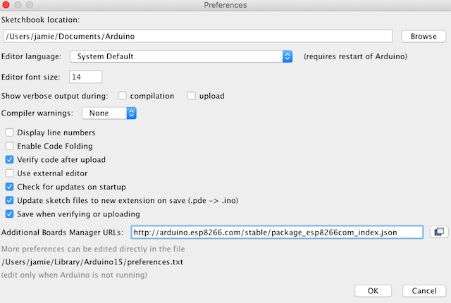
Before getting on with coding, you need to make some preparations. If you haven't already, set up the Arduino IDE to recognize your NodeMCU board. You can add it to your boards list via File > Preferences.
You can find a more detailed explanation of this step in our NodeMCU introduction article.
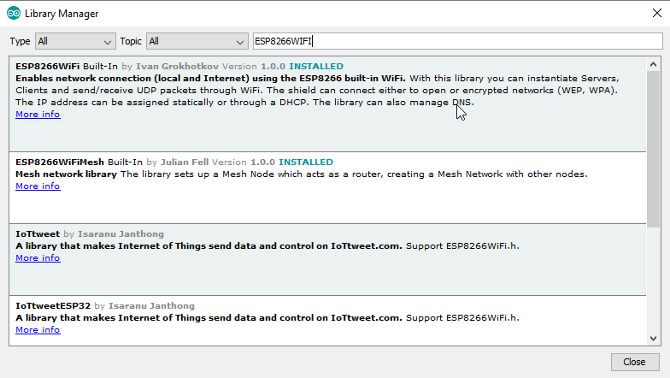
Two libraries are required for this project. Navigate to Sketch > Include Library > Manage Libraries. Search for ESP8266WIFI by Ivan Grokhotkov and install it. This library is written for making Wi-Fi connections with the NodeMCU board.
Next search for the IFTTTWebhook by John Romkey and install the latest version. This library is designed to simplify the process of sending webhooks to IFTTT.
That's all the preparation we need, lets code!
How the Code Will Work
We'll use the ESP8266WIFI library to establish a Wi-Fi connection. The IFTTTWebhooks library makes a request to IFTTT---in this case, to post to Twitter. Then, instruct the NodeMCU board to sleep when not in use to save power.
When the button is pressed, it will link the D0 and RST pins. This resets the board, and the process happens again.
Most of the code in this tutorial is simple enough for beginners. That said, if you are starting out, you'll find it a lot easier to understand after following our Arduino beginners guide.
This tutorial goes through the code in chunks to help with understanding. If you want to get straight to business, you can find the complete code at Pastebin. Note that you will still need to fill in your Wi-Fi and IFTTT credentials in this code for it to function!
Step 3: Testing Deep Sleep
To begin, we'll create a simple test to show how deep sleep works. Open a new sketch in the Arduino IDE. Enter the following two code chunks.
            #include <IFTTTWebhook.h>
#include <ESP8266WiFi.h>

#define ledPin 5
#define wakePin 16
#define ssid "YOUR_WIFI_SSID"
#define password "YOUR_WIFI_PASSWORD"
#define IFTTT_API_KEY "IFTTT_KEY_GOES_HERE"
#define IFTTT_EVENT_NAME "IFTTT_EVENT_NAME_HERE"
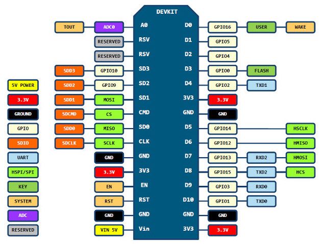
Here, we include our libraries, along with defining a few variables we will need in our sketch. You'll notice that the ledPin and wakePin are numbered differently here compared to the Fritzing diagram above. The NodeMCU has a different pinout to Arduino boards. This is not a problem though, due to this handy diagram:
Now create a setup function:
            void setup() {
  Serial.begin(115200);
  while(!Serial) {
  }
  Serial.println(" ");// print an empty line before and after Button Press
  Serial.println("Button Pressed");
  Serial.println(" ");// print an empty line
  ESP.deepSleep(wakePin);
}
Here, we set up our serial port, and use a while loop to wait until it begins. Since this code will trigger after pressing the reset button, we print "Button Pressed" to the serial monitor. Then, we tell the NodeMCU to go into deep sleep until the button connecting the wakePin to the RST pin is pressed.
Finally, for testing, add this to your loop() method:
            void loop(){
  //if deep sleep is working, this code will never run.
  Serial.println("This shouldn't get printed");
}
Usually, Arduino sketches run the loop function continuously after setup. Since we send the board to sleep before setup ends, the loop never runs.
Save your sketch and upload it to the board. Open the serial monitor and you should see "Button Pressed." Every time the button triggers, the board resets and the message prints again. It works!
A Note About the Serial Monitor
You may have noticed some nonsense characters in the serial monitor during some of your projects. This is usually due to not setting the serial monitor to the same baud rate as the Serial.begin(XXXX) rate.
Many guides suggest starting the serial connection at a baud rate of 115200 for a project like this. I tried many combinations, and they all had varying degrees of gibberish before and after serial messages. According to various forum posts, this could be down to a faulty board or software compatibility issue. As it doesn't affect the project too badly, I'm choosing to pretend it's not happening.
If you are having issues with the serial monitor, try different baud rates and see which works best for you.
Step 4: Connecting to Wi-Fi
Now create a function for connecting to your Wi-Fi network.
            void connectToWifi() {
  Serial.print("Connecting to: SSID NAME"); //uncomment next line to show SSID name
  //Serial.print(ssid);
  WiFi.begin(ssid, password);
  Serial.println(" ");// print an empty line
  Serial.print("Attempting to connect: ");

  //try to connect for 10 seconds
  int i = 10;
  while(WiFi.status() != WL_CONNECTED && i >=0) {
    delay(1000);
    Serial.print(i);
    Serial.print(", ");
    i--;
  }
  Serial.println(" ");// print an empty line

  //print connection result
  if(WiFi.status() == WL_CONNECTED){
    Serial.print("Connected.");
    Serial.println(" ");// print an empty line
    Serial.print("NodeMCU ip address: ");
    Serial.println(WiFi.localIP());
  }
  else {
    Serial.println("Connection failed - check your credentials or connection");
  }
}
This method attempts to connect to your network ten times with a second in between. Success or failure of connection prints to the serial monitor.
Step 5: Calling the Connection Method
Right now, the connectToWifi() is never called. Add a call to your setup function between the "Button Pressed" message and sending the board to sleep.
connectToWifi();
In case you are wondering where this fits, it should look like this:
At the top of the sketch replace the ssid and password variables with your Wi-Fi credentials. Save your sketch and upload to the board.
Now when the board boots it will attempt to connect to your Wi-Fi network, before returning to the setup function. Now, lets set up the IFTTT integration.
Step 6: Setting Up IFTTT Integration
IFTTT allows integration with a vast array of web services. We used it in our Wi-Fi PC tower LED tutorial to send an alert whenever a new email is received. Today we'll be using it to send a tweet at the press of a button.
Navigate to the My Applets page, and select New Applet
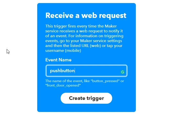
Click on +this and connect to Webhooks. Select "Receive a web request" and name your event. Keep it simple! Note down the event name, you'll need to add it to your NodeMCU code later. Click "Create Trigger".
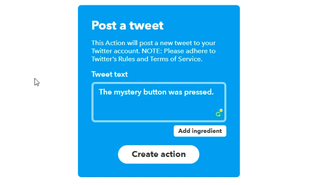
Now select +that. Search for the Twitter service and connect to it---you will need to authorize it to post to your Twitter account. Select "Post a tweet" and choose your message.
The next screen will ask you to review the applet. Click finish. That's it!
Step 7: Adding IFTTT Credentials to the Code
Back in the Arduino IDE you will need to add your IFTTT API key and event name to your defined variables. To find the API key, navigate to My Applets and select Webhooks under the Services tab. Select Documentation to access your key.
Copy the key, and event name into your code, replacing the temporary names set up for them.
            #define IFTTT_API_KEY "IFTTT_KEY_GOES_HERE"
#define IFTTT_EVENT_NAME "IFTTT_EVENT_NAME_HERE"
Note, the inverted commas have to stay, only replace the text.
Between calling the connectToWifi() and sending the board to sleep, create an instance of the IFTTTWebhook library object. The LED signals task completion before deep sleep begins again.
            //just connected to Wi-Fi
IFTTTWebhook hook(IFTTT_API_KEY, IFTTT_EVENT_NAME);
hook.trigger();

pinMode(ledPin, OUTPUT);
digitalWrite(ledPin, HIGH);
delay(200);
digitalWrite(ledPin, LOW);
//now sending board to sleep
Calling trigger on the hook object fires off the IFTTT applet, and should post to your Twitter account. Save your sketch and upload it. You now should have a fully functional tweeting button.
If it doesn't seem to be working, check through your code and credentials carefully for mistakes. If you really get stuck, get the full code from above and compare it to your own.
Done! How Could You Improve It Further?
This is a basic version of a Wi-Fi button, but there are many ways it could be improved. For simplicity, the USB connection is used for power here. A battery would make it entirely mobile, and a case holding the circuit would be the perfect beginner 3D printing project.
Despite using deep sleep, you may find a battery would run out quite quickly. There are many Arduino power saving tips that help in these type of projects. While more difficult than this tutorial, if you made your own power-conscious Arduino from scratch, a battery-powered Wi-Fi button could last for months!
This project would make the perfect for a remote for smart home applications. There are already a considerable amount of home automation applets available on IFTTT. Once you've got the basics down, you can use almost any sensor or switch to trigger practically any service you can imagine.
Image Credit: Vadmary/Depositphotos

