A bench power supply is an extremely handy bit of kit to have around for electronics hobbyists, but they can be expensive when purchased new. If you have an old computer ATX PSU lying around, you can give it new life as a bench power supply. Here's how.
Like most computer components, power supply units (PSUs) get outdated. When you upgrade, you may find you no longer have the right connectors - or that your shiny new graphics card requires far more power than your puny old PSU can handle - a dual GPU setup can easily rack up 1,000 watts. And, if you're anything like me, you have a stash of old PSUs hoarded away in a cupboard somewhere. Now's your chance to use one of them.
A bench PSU is basically just a way of providing a variety of different voltages for test purposes - perfect for those us who are constantly playing with Arduinos and LED strips. Conveniently, that's exactly what a computer power supply does too - only with a lot of different connectors and coloured wires.
Today, we're going to strip the PSU to its bare essentials, then add some helpful sockets onto the case that we can plug projects into.
Warning
Ordinarily, you'd never open a power supply unit. Even when the power is off, there are large capacitors that can store lethal electric current for weeks, sometimes months, after being turned on. Take extreme care when working with a power supply unit and ensure it's been dormant for at least three months before opening the case, or make sure you're wearing heavy rigging gloves when poking around in there. Proceed with caution.
Also, note that this will irrevocably damage the PSU, so you won't ever be able to use it in a computer again.
Components Needed
- Two 2.1mm barrel jack and socket - I'll be powering the Arduino directly with this. Two barrel jack plugs will be used to make a male-male power cable.
- Variety of 2mm coloured sockets, such as this one (can be used with banana plugs). You may prefer terminal posts.
- Heat shrink tubing, 13mm x 1m (and smaller, if you can afford to buy more).
- SPST (single pole single throw) rocker switch. I used an illuminated one to serve the dual function as power on light too.
- 10w 10 Ohm wire wound resistor.
Construction
Unscrew and remove the top half of the power supply case. You may need to pull a plug out of the main circuitry to fully separate the covers.

These are nasty capacitors which hold huge amounts of electricity:

Strip the plugs and pull the wires through the hole in the case.

Next, bunch them with cable ties according to colour, just to make things a little more organised. As a general rule:
- Black: Ground
- Red: + 5V
- Yellow: +12V
- Orange: +3.3V
- White: -5V
- Blue: -12V
- Purple: +5V standby (not used)
- Grey: power on indicator
- Green: ON/OFF switch

Exactly which power lines you choose to connect up is your choice, but I decided to only work with the 3 positive lines - 3.3, 5, and 12V. I also won't be using the purple or grey wires, instead wiring a 12V illuminated switch.
Use HSS drill bits to cut appropriately-sized holes in the metal - the 2mm plugs and DC barrel required 8mm holes. Clamp the case down with a piece of wood underneath. Making the hole for the rocker switch was a lot more difficult, but you should be able to use a smaller drill bit to cut out as much as you can, then file the remainder away with a hobby drill and grinder.

Pulling the wires through the appropriate holes and soldering the sockets before pushing them into the case is probably a good idea; I didn't do that.

The GND, +3.3V, +5V, and +12V plugs should be easy to wire up. Remember to cut a small piece of heat shrink tube and thread the bunched wires through it before soldering them to the terminals!
The DC barrel plug is a little more complicated. Since this will be used to power an Arduino, which is centre positive, you should connect some yellow cables to the centre pin. You may have heard the Arduino can be powered by 9V external source, but the on-board power regulator actually allows for 9-12V, so the 12V from a desktop PSU should be fine. Barrel jacks have 3 pins, but only one of which is obviously connected to the centre. You should see a circular metal bit, but check where you purchased from if you're not sure. The other two pins are GND, and both should be connected. Again, use heat shrink tubing to ensure the centre and outer pins don't accidentally connect.
Power Switch and Indicator
The green wire acts as a power on switch - simply ground it to turn on the PSU. This is unlike a regular power switch, would would actually cut the power coming from the source. The addition of illumination makes this the most complex part of the project.
Illuminated SPST switches should have 3 terminals: one will be indicated either by a different colour or labelled and GND. The terminal opposite would normally be wired with 12V, then the rest of your circuit would be powered from the centre pin. Switching it would provide power to the circuit, as well as draw a little for the light. However, this is isn't going to work for us. Instead, reverse the GND and 12V line. Use a single 12V cable (yellow) on the coloured terminal of your rocker switch (or the one labelled GND). Pull a black wire (GND) to the pin opposite; and put the green cable to the centre pin.

Now when the switch is pushed, the LED will still be lit, but instead of 12V being sent back out to the centre pin, the GND will be shorted with PWR ON, resulting in our PSU activating.
Shrink Them Tubes!
Finally, with your heat shrink tubing neatly pulled down to cover the switches and solder points, use a localised heat gun to shrink them. This bit is actually quite fun to watch.
Before:

And after:

Lastly, The Fake Load
Many power supplies require a load to stay on - in this case, we can use a 10W 10 Ohm resistor to do the job. Wire it between the 5V (red) and GND lines. It'll produce a small amount of heat but should be fine with the fan on.

I finished up by tying together any loose cables and covering them to ensure they didn't touch other internal parts, then put everything back together again for test.

I mixed up which side to place the plugs and button on, so they ended up being located on the cramped side, some right above the AC power socket. This is, of course, a stupidly dangerous thing to do, as the AC soldered pins might pierce the or touch the DC power plugs, sending a nasty surprise to either myself or my Arduino. I solved this by gluing a bit of thick plastic between them, but it's not ideal. Think twice before drilling and make sure your sockets go on the correct side!
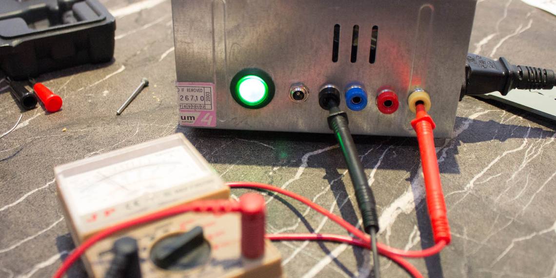
It was also at this point that I realised why this PSU had been shelved in the first place - the fan wasn't running. No worries - the fan itself was fine, but the controller circuit was broken, so I opened it back up and spliced the fan directly to one of the 12V lines. Finally, I did some testing with a multimeter to ensure voltages were correct.

I now have a permanent bench power supply for electronics projects, and can do away with constantly plugging in various adapters. It's been a learning experience, and mistakes were made: you should learn from them. Let us know how yours turns out!