Have you always wanted to design your own 3D models? What about 3D printing a part you have designed? There are many 3D modeling programs around, but these can be difficult to use if you are not artistic (like me). OpenSCAD provides a way for you to design models specifically for 3D printing, using nothing but code. Don't worry if you don't know how to code either, today I'll be guiding you through the basics.
What Is OpenSCAD?
OpenSCAD is a free Solid Computer Aided Design modeller. It's available for Windows, Mac, and Linux. What makes it different to many other programs is that you design parts using code instead of a mouse. This makes it very easy to do mathematical calculations, store dimensions in variables, resize parts, and more.
There are some factors you need to account for when 3D printing models, but many of these apply to 3D printing CAD models in general, not just OpenSCAD designs. If you want to know more about 3D printing, checkout our Ultimate Beginner's guide. If you're looking for a more interactive modeller, read out guide to creating objects in Sketchup.
Getting Set Up
First, head on over to the downloads page and find a version of OpenSCAD suitable for your operating system. I'm using Mac OS, but these OpenSCAD principles apply to all systems.
Once installed, go ahead and open it. You will be presented with this startup menu:

This shows you the files you opened last, and gives you the option to load a few examples. Feel free to look around some of the examples, however I found these made things more confusing when first starting out. For this tutorial, create a new file by clicking the new button.
Once open, you will be presented with this bare-looking interface:

This is split into three main areas. On the left is your editor and menu. This is where you will write your code.This will not have any code in yet, as you are creating a new file. At the top, there are some menu buttons to perform basic tasks, such as load, save, undo, and so on.

The bottom right is the console. This will show you any errors in building the model.

The final section is the main interface on the top right. Here you can interact with your model, but you won't be able to edit it here (you will be writing code to do this).

There are several buttons at the bottom of this main interface. These primarily allow you view your design in different ways.
Go ahead and save a new file by pressing the save button in the editor menu or by going to File > Save.
The Basics
The way OpenSCAD works the majority of the time is through the addition and subtraction of simple shapes. You can build very complex models this way, so let's jump right in.
Here's the first shape, a simple box:

And here's the code to produce that:
cube(); // create a cube
To get your code to execute and build the model, you need to preview it. OpenSCAD will do this by default every time you save, or you can press F5 to force a refresh. Experiment with moving around in 3D space by holding down the left or right mouse buttons.
Now, this produces a nice cube, but it's not terribly useful without any dimensions. OpenSCAD does not work in any particular measurement system, instead, units are all relative to each other. You can create a box 20 x 10, and it's up to any other program (such as your 3D printing slicer) to interpret these, be that metric or imperial. It actually provides great flexibility.
Let's add some dimensions to your cube. You do this be passing in parameters to the cube method:
cube(size = [10, 20, 30]); // rectangle
The values 10, 20, and 30 represent the size of the cube in the X, Y, and Z axis. Notice how this has produced a much larger rectangle:

By default, OpenSCAD draws components from the bottom left. You can adjust this by setting the center parameter to true. Here's the code to do that to the rectangle:
cube(size = [10, 20, 30], center = true); // rectangle centered
And here's what it looks like:

Centering objects works well for simple shapes, but it makes things complicated for non symmetrical objects. You will need to decide which method works best for you.
Moving on to a more complex shape, here's a cylinder:

Here's the code to create it:
cylinder(d = 10, h = 10, center = true); // cylinder
Unlike cubes, cylinders are automatically drawn in the center of the X and Y axis. The d parameter stands for diameter (you can pass in the radius instead if you prefer). The h parameter is the height. Something is wrong here though. This cylinder looks quite "blocky". You need to increase the number of faces drawn on the circumference. This is easy to do -- add the following parameter to your cylinder code.
$fn = 100
So the cylinder definition becomes:
cylinder(d = 10, h = 10, center = true, $fn = 100);
Here's what that looks like:

This increases the number of faces needed to make circles -- 100 is a good starting point. Keep in mind, that this will greatly increase rendering times, particularly on complex models, so it's usually best to leave this out until you have finished designing.
It's easy to apply transformations on shapes. You need to call special methods before creating your shapes. Here's how to rotate the cylinder using the rotate method:
rotate(a = [0, 90, 0]) cylinder(d = 10, h = 10, center = true); // rotated cylinder
The values passed to the a parameter represent the angle of rotation of the X, Y, and Z axis. Here's the result:

Another very useful function is translate. This allows you to move objects around in 3D space. Once again, you will need to pass in the amount of movement for each axis. Here's the result:

Here's the code:
translate(v = [0, 25, 0]) cylinder(d = 10, h = 10, center = true); // translated cylinder
Understanding the translate method is one of the most important things you can do. It's required for designing most complex designs.
Finally, another useful shape is a sphere:

Here's the code:
sphere(d = 100);
Just like the cylinder, you can smooth this out using the $fn code above.
Advanced Coding
Now that you know the basics, let's look at some more advanced skills. When designing a part, it helps to have a think about how it could be made up from smaller shapes and objects. You don't have to do this, and you can "make things up" as you go, but it does help to have a rough plan -- even if it's only in your head.
Let's create an advanced shape: a cube with a hollowed out sphere interior. Create a cube and a sphere with center set to true. Subtract one from the other using the difference method:
            difference() {
    // subtraction
    cube(size = [50, 50, 50], center = true); // outer cube
    sphere(d = 65, center = true); // inner sphere
}
Here's the result:

Experiment with the diameter (d parameter) of the sphere and see what happens.
In OpenSCAD, there are usually many ways to accomplish the same task. If you wanted a groove in a cube, you could subtract another cube from it, or add two more above it. It does not usually matter which way things are done, but depending on the complexity of the part, it may be easier to do certain manipulations first.
Here's how to create a channel in a cube. Instead of using another cube, using a cylinder will create a rounded channel. Notice how the difference method is used once again, and how the translate and rotate methods are used to manipulate the shapes. Using the rotate method often makes transformations tricky, so play around with the parameters until you achieve your desired result. Here's the code:
            difference() {
    // subtraction
    cube(size = [50, 150, 50]); // outer cube
    translate(v = [25, 150, 50]) rotate(a = [90, 0, 0]) cylinder(d = 40, h = 150); // cylinder channel
}
Here's what that looks like:

You may be wondering what all the green stuff is. This is here because the 3D model is just a preview right now. To fix this, press F6 to fully render the model. This can take some time, depending on the complexity. The preview (F5) is usually good enough while working. Here's what the final render looks like (with $fn set to 100):

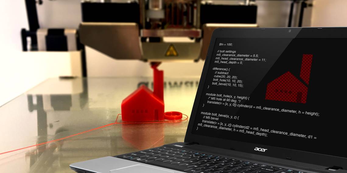
Here's another advanced example. Say you wanted a mount something using a bolt. Creating a hole is simple enough using cylinder, but what if you wanted the bolt head flush mounted for countersunk bolts? You could simply create a large cylinder for the bolt head to sit in, but that would not look very nice. The solution is a chamfer, which you can create with the cylinder method. The trick here is to specify two diameters -- d1 and d2. Make these different sizes, and OpenSCAD will do the rest.
As I'm British, I'll be using metric dimensions here, for an M5 countersunk bolt. You could easily adjust this to fit whatever fixings you want to use. Here's the code:
            $fn = 100;

// bolt settings
m5_clearance_diameter = 5.5;
m5_head_clearance_diameter = 11;
m5_head_depth = 5;

difference() {
    // subtract
    cube(20, 20, 20);
    bolt_hole(10, 10, 20);
    bolt_bevel(10, 10, 15);
}

module bolt_hole(x, y, height) {
    /* M5 hole at 90 deg. */
    translate(v = [x, y, 0]) cylinder(d = m5_clearance_diameter, h = height);
}

module bolt_bevel(x, y, z) {
    // M5 bevel
    translate(v = [x, y, z]) cylinder(d2 = m5_head_clearance_diameter, d1 = m5_clearance_diameter, h = m5_head_depth);
}
Notice how the bolt dimensions are stored in variables? This makes coding and maintenance much easier. One method you may not have come across yet is module. This allows you to define a block of code to execute whenever you like. In reality, this is a function. You should use modules and variables for any complex shape, as they make things easier to read, and quicker to make any changes. Here's what the chamfer looks like:

Let's look at one final example. Say you wanted to produce a series of holes around a circle. You could manually measure, translate, and rotate all of these, but even with modules this would be tedious. Here's the end result, 10 cylinders even distributed around a circle:

Here's the code:
            $fn = 100;
number_of_holes = 10;

for(i = [1 : 360 / number_of_holes : 360]) {
    // number_of_holes defines number of times this code runs
    make_cylinder(i);
}

module make_cylinder(i) {
    // make cylinder and even distribute
    rotate([0, 0, i]) translate([10, 0, 0]) cylinder(h = 2, r = 2);
}
This code is simpler than you would expect. A for loop is used to call the make_cylinder module ten times. As there are 360 degrees in a circle, and 360 / 10 = 36, each cylinder needs to be rotated in increments of 36 degrees. Each iteration of this loop will increment the i variable by 36. This loop calls the make_cylinder module, which simply draws a cylinder and positions it according to the degrees passed to it by the loop. You can draw more or less cylinders by modifying the number_of_holes variable -- although you may want to adjust the spacing if you do so. Here's what 100 cylinders look like, they overlap slightly:

Exporting
Now that you know how to code in OpenScad, there's one last step required before you can 3D print your models. You need to export your design from OpenSCAD into the standard STL format used by most 3D printers. fortunately, there's an export to STL button: Editor Menu > Top Right:

That's it for today. You should now have an excellent working knowledge of OpenSCAD -- all the complex stuff builds upon these foundations, and many complex shapes are really lots of simple shapes combined.
For a challenge, why not look at some of our 3D printing projects, and try to recreate the parts in OpenSCAD:
- 3D Printables for Tabletop Fantasy RPGs
- Custom Shortcut Buttons
- Electronic D20
- Games You Can 3D Print
Did you learn any new tricks today? What's your favorite OpenSCAD feature? Will you be switching from another CAD tool soon? Let us know in the comments below!