The Raspberry Pi Pico is a powerful, low-cost microcontroller board that can be used as the brains for a variety of electronics projects. In addition, there's already a wide range of add-ons and accessories available for it.
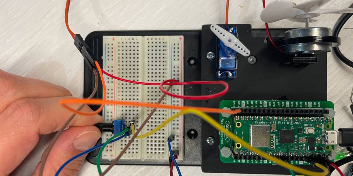
One such add-on is the Kitronik Inventor's Kit for Raspberry Pi Pico. The kit includes a booklet, breakout board, breadboard, and various electronics components to ensure hours of learning ahead. Let's take a closer look.
What Can I Build With the Kitronik Inventor’s Kit?

The Kitronik Inventor's Kit comes with (almost) everything you need to play the role of inventor:
- Pin breakout PCB for Raspberry Pi Pico
- Servo
- Mini display
- Zip stick (with pins)
- LEDs
- Resistors
- Fan blade and motor
- Jumper wires
- Buzzer
- Capacitors
- Terminal connector
- Potentiometer
To complete this kit, all you need is a Raspberry Pi Pico with GPIO pin headers soldered to it. If this is your first time applying solder, don't be nervous: check out our guide on how to solder header pins on a Raspberry Pi Pico.
Performing Experiments
The kit's booklet has great step-by-step instructions, picture references, as well as explanations breaking down the code elements to reinforce your learning. Ten interactive experiments will familiarize you with such techniques as digital inputs and outputs, using a potentiometer to dim an LED light, using transistors to drive a motor, variable speed wind power, making music with a buzzer, and more.
The example projects for the kit are programmed using the MicroPython language, a variant of Python for microcontrollers. Learn how to get started with MicroPython on the Raspberry Pi Pico.
Blink LED, Blink!

Let's ease in by getting the Pi Pico's onboard LED to blink. In the project introduction, you'll notice a quick summary of what is expected to happen, along with an explanation of what's going on.
The code shown in the image above includes a slight variation for the Pi Pico W, which has an internal connection to the LED. If you have purchased the standard Pi Pico (without Wi-Fi capabilities), refer to the onboard LED with the following code instead:
LED = machine.Pin(25, machine.Pin.OUT) #Set up the onboard LED Pin as an output
You'll need to press the Stop button in the Thonny IDE to prevent the code from running forever. Challenge yourself to stop this process whenever a keyboard button is pressed.
Use a Switch to Turn the LED On and Off

As you work your way through the booklet, you'll notice that the author guides you to incrementally build upon your knowledge. In this experiment, you will build on the existing code to control the LED by using conditional statements within a while True infinite loop.
Digital input and output signals are used as you press the switch to turn the Pi Pico's LED on and off. Simply stated, when you press the switch with your finger, it completes the circuit and 3.3V is sent to the connected GPIO input pin on the Pico. The code's if condition is then met and the LED is switched on. When the button is not pressed, the elif condition is met and the LED is turned off.

Your journey with circuits, breadboards, and everything in between begins. If you get stuck, follow the experiment link written in the included booklet for help.
Light, Sensor, Action!
Although some may think that controlling an LED with your hand is magic, it is actually a phototransistor that's detecting light. By placing an object (such as your hand) to block direct light, the phototransistor will react and turn the Pi Pico LED on. This is really similar to how your car's dashboard sensor turns on the vehicle's headlights automatically at night. This project will have you using some jumper wires, a resistor, and phototransistor.

This experiment focuses on an analogue input, depending on which the LED light level will be adjusted (based on the perceived brightness of your room). As you'll recall, the switch used previously used a digital signal (on or off only). This time, you're using one of the Pico's ADC (analogue to digital converter) channels to measure a varying analogue signal from the phototransistor.

When the level is below a certain threshold, the onboard LED is then switched on; if it's above the threshold, the LED is switched off. Feel free to change the lightLevelToSwitchAt value in the code to another number. Do you still see the same effect?
Two Heads Are Better Then One

In situations where problems will occur, it's often nice to have a second set of eyes reviewing your Python code (especially when someone finds the Reddit thread explaining the LED wiring differences between the Pi Pico and Pi Pico W).
In this case, pairing backgrounds of electrical engineering and Linux administration together should result in well-rounded sessions of tinkering and exploring puzzles on a Friday night. With that said, when both members of the team are wrong, all that's left to do is race to your favorite search engine and wager who stumbles upon the answer first. If you get stuck, you can always head to the Kitronik learning resources for tips and tricks too.
What Are You Looking Forward to Tackle First?
In the last experiment you'll get to create a "wind turbine" which brings all the lessons into a final celebration of your new-found knowledge. Do you prefer working with digital signals? Perhaps, you enjoy feeling like a magician while waving your hand over a phototransistor to manipulate the brightness of the LED light?
If you're super creative, there's a potential of being able to recreate an 8-bit version of your favorite theme song with the buzzer. That is, if you can get nail the right frequencies of each note.
Exploring Electronics With Pico
This only cracks the surface of what you can do with the Raspberry Pi Pico and the Kitronik Inventor's Kit. There are many more electronic experiments to explore. Alternatively, there are other kits and breakout boards available for the Pico. If you're feeling confident, you could simply connect the Pico to a standard breadboard to wire up electronic components bought separately. Or you could use it for many other projects, such as retro gaming, music, and home automation.