Whether it be computer peripherals, smart appliances, Internet of Things (IoT) devices, or electronic measuring tools, they all use serial communication protocols to connect different electronic components together.
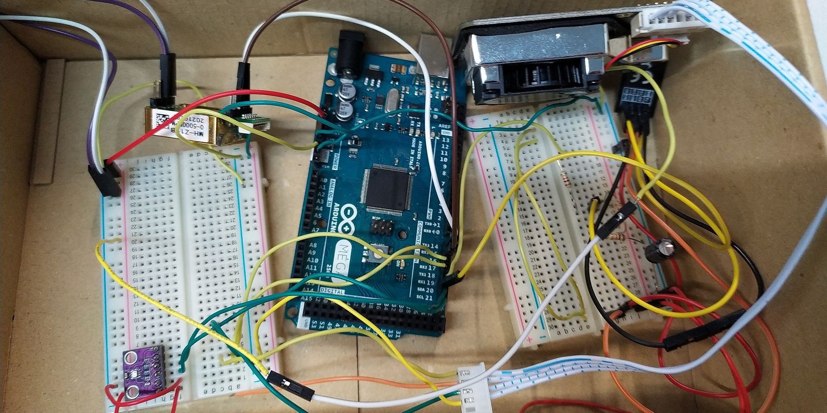
These components usually consist of a microcontroller and slave modules such as a fingerprint sensor, an ESP8266 (Wi-Fi module), servos, and serial displays.
These devices use different kinds of communication protocols. Below you will learn about some of the most popular serial communication protocols, how they work, their advantages, and why they remain in use.
What Is Serial Communication?
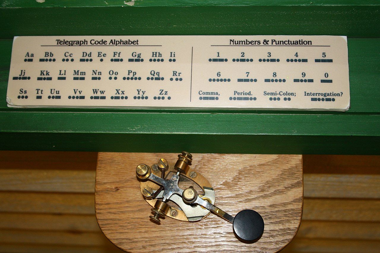
Serial communication protocols have been here ever since the invention of the Morse Code in 1838. Today, modern serial communication protocols use the same principles. Signals are generated and transmitted on a single wire by repeatedly shorting two conductors together. This short acts like a switch; it turns on (high) and off (low), providing binary signals. How this signal is transmitted and received will depend on the type of serial communication protocol used.
With the invention of the transistor and the innovations that followed, engineers and tinkerers alike made processesing units and memory smaller, faster, and more power-efficient. These changes demanded bus communication protocols to be as technologically advanced as the components being connected. Thus the invention of serial protocols such as UART, I2C, and SPI. Although these serial protocols are several decades old, they are still preferred for microcontrollers and bare-metal programming.
UART (Universal Asynchronous Receiver-Transmitter)
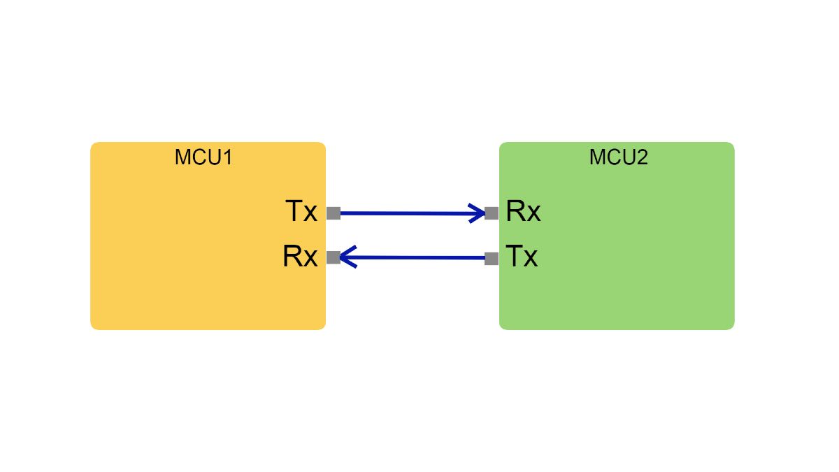
The UART protocol is one of the oldest yet most reliable serial communication protocols we still use today. This protocol uses two wires known as Tx (transmit) and Rx (Receive) for both components to communicate.
To transmit data, both the transmitter and the receiver must agree with five common configurations, these are:
- Baud Speed: The transmission speed of how fast data is to be transmitted.
- Data Length: The agreed number of bits that the receiver will save into its registers.
- Start Bit: A low signal that lets the receiver know when data is about to be transferred.
- Stop Bit: A high signal that lets the receiver know when the last bit (most significant bit) has been sent.
- Parity Bit: Either a high or low signal used for checking if data sent was correct or corrupted.
Since UART is an asynchronous protocol, it doesn’t have its own clock that regulates data transmission speed. As an alternative, it does utilize baud rate for timing when a bit is being transmitted. The usual baud rate used for UART is 9600 baud, meaning a transmission rate of 9600 bits per second.
If we do the math and divide one bit by 9600 baud, we can calculate how fast one bit of data is transmitted to the receiver.
1/9600 = 104 microseconds
This means that our UART devices will start counting 104 microseconds to know when the next bit will transmit.
When UART devices have been connected, the default signal is always raised to high. When it detects a low-frequency signal, the receiver will start counting 104 microseconds plus another 52 microseconds before it starts saving the bits into its registers (memory).
Since it was already agreed upon that eight bits was to be data length, once it saved eight bits of data, it will start checking for parity to check if data is odd or even. After the parity check, the stop bit will raise a high signal to notify the devices that the entire eight bits of data was successfully transmitted to the receiver.
Being the most minimalist serial protocol utilizing only two wires, UART is commonly used today in smart cards, SIM cards, and automobiles.
SPI (Serial Peripheral Interface)
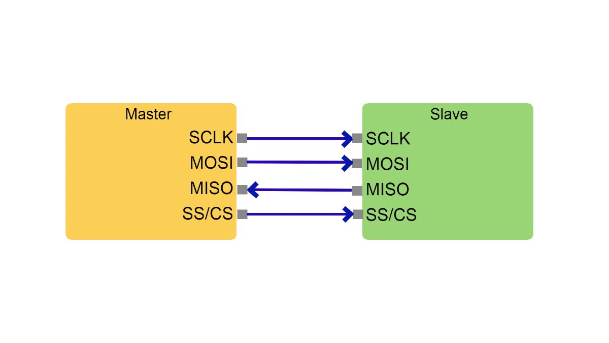
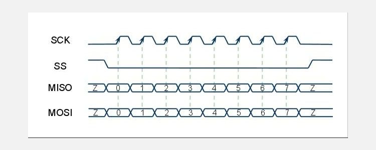
SPI is another popular serial protocol used for faster data rates of about 20Mbps. It uses a total of four wires, namely SCK (Serial Clock Line), MISO (Master Out Slave In), MOSI (Master In Slave Out), and SS/CS (Chip Select). Unlike UART, SPI uses a master-to-slave format to control multiple slave devices with only one master.
MISO and MOSI act like the Tx and Rx of UART being used to transmit and receive data. Chip Select is used for selecting which slave the master wants to communicate with.
Since SPI is a synchronous protocol, it uses a built-in clock from the master to ensure both the master and slave devices are running on the same frequency. This means that the two devices no longer need to negotiate a baud rate.
The protocol starts with the master selecting the slave device by lowering its signal to the specific SS/CK connected to the slave device. When the slave receives a low signal, it starts to listen to both the SCK and MOSI. The master then sends a start bit before sending the bits that contain data.
Both MOSI and MISO are full-duplex, meaning they can transmit and receive data at the same time.
With its ability to connect to multiple slaves, full-duplex communication, and lower power consumption than other synchronous protocols like I2C, SPI is used in memory devices, digital memory cards, ADC to DAC converters, and crystal memory displays.
I2C (Inter-Integrated Circuit)
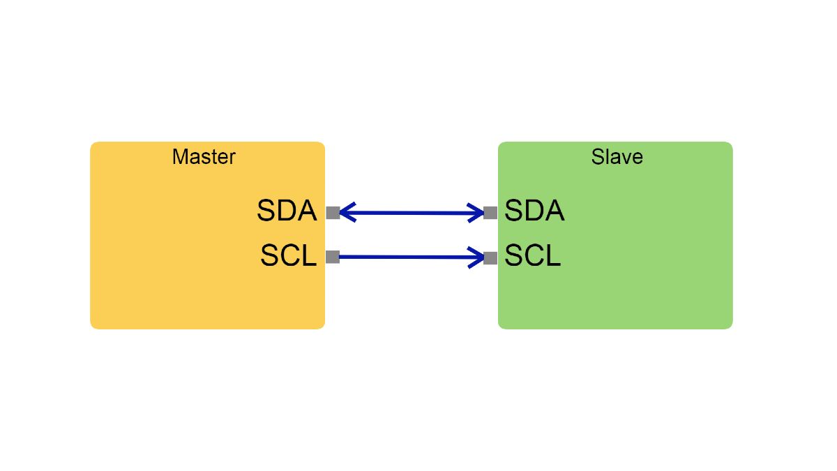
I2C is yet another synchronous serial protocol like SPI, but with several advantages over it. These include the ability to have multiple masters and slaves, simple addressing (no need for Chip Select), operating with various voltages, and using only two wires connected to two pull-up resistors.
I2C is often used in many IoT devices, industrial equipment, and consumer electronics.
The two pins in an I2C protocol are the SDA (Serial Data Line) which transmits and receives data, and the SCL (Serial Clock Line) pin, which functions as a clock.
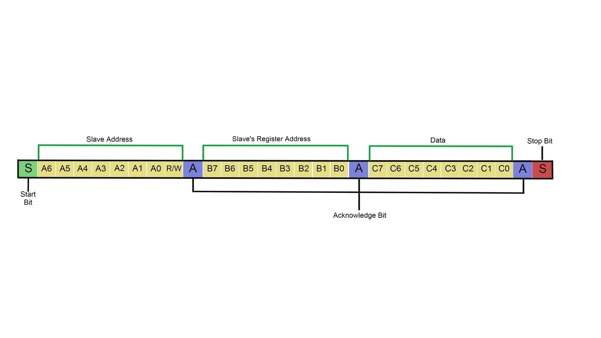
- The protocol starts with the master sending a start bit (low) from its SDA pin, followed by a seven-bit address that selects the slave, and one bit to for selecting read or write.
- After receiving the start bit and address, the slave then sends an acknowledge bit to the master and starts listening to the SCL and SDA for incoming transmissions.
- Once the master receives this, it knows the connection has been made to the correct slave. The master will now select which specific register (memory) from the slave it wants to access. It does so by sending another eight bits specifying which register is to be used.
- Upon receiving the address, the slave now readies the select register before sending another acknowledge to the master.
- Having selected which specific slave and which of its registers to use, the master finally sends the data bit to the slave.
- After the data is sent, a final Acknowledge bit is sent to the master before the master ends with a stop bit (high).
Why Serial Communications Are Here to Stay
With the rise of parallel and many wireless protocols, serial communications have never fallen out of popularity. Generally using only two to four wires for transmitting and receiving data, serial protocols are an essential mode of communication for electronics that only have a few ports to spare.
Another reason is its simplicity which translates to reliability. With only a few wires sending data once at a time, serial has proven its reliability to send the complete packets of data without any loss or corruption when transmitted. Even at high frequencies and longer range communication, serial protocols still beat many modern parallel communications protocols available today.
Although many might think that serial communications like UART, SPI, and I2C have the disadvantage of being old and outdated, the fact remains that they have proven their reliability over several decades. Protocols being this old without any real replacement only suggests that they are, in fact, indispensable and will continue to be used in electronics for the foreseeable future.

