Whether it be your smartphone, computer, speakers, or the common light bulb, every electrical device needs a specific amount of electricity to function. This electricity needs to be regulated to ensure your device works properly. Too much and the device breaks down; too little and it may not work at all.
A multimeter is a tool used to measure the amount of electricity going through a certain component by measuring current (amperes), electric pressure (voltage), resistance (ohms), and continuity.
If you are interested in checking, troubleshooting, or designing your DIY electronics/electrical projects, a multimeter is an essential tool you must have.
Getting Acquainted With the Multimeter
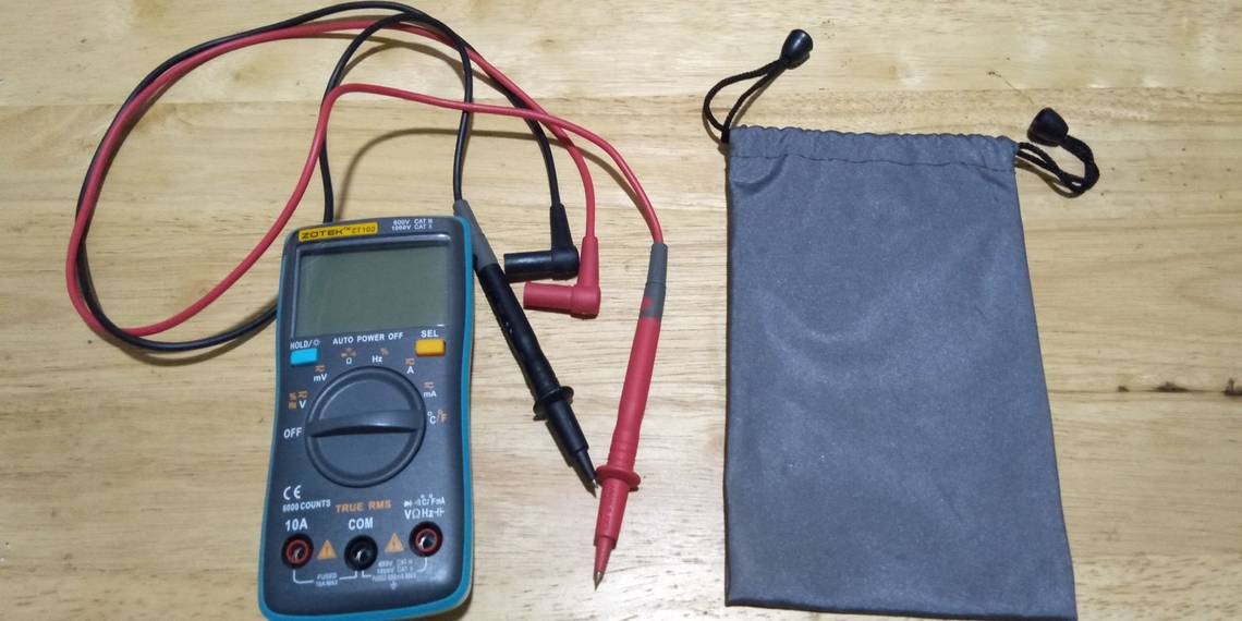
Before measuring anything with the device, you'll first have to acquaint yourself with the common parts and functionalities of a multimeter.
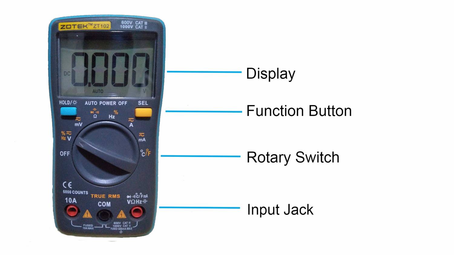
Display/Scale: A display or scale is where you will see the values of your measurements.
Rotary Switch: The rotary switch allows the user to switch between the type of measurements they are trying to test. This would include valuable measurements such as voltage, resistance, and current.
Function Button: Some values provided by the rotary switch will have multiple functions. Use the function button to switch between these functions.
Input Jacks: The input jacks are where you will insert your testing probes. Most multimeters will have three input jacks. Multimeters typically come with two testing probes. The black testing probe will always be inserted in the COM (common) input jack. Unless you are trying to measure current that is measurable by more than a one ampere, your red testing probe should always be inserted at the rightmost input jack where it can measure voltage, resistance, continuity, and currents measurable in milliamps.
Learning Through Practical Application of a Multimeter
The best way to learn is by applying. Today you will learn how to use a multimeter by measuring the values of this DIY emergency modem power supply.
The goal is simple. Take a 20-volt power tool battery and lower its voltage to meet the power requirements of a 12-volt modem. This project will use a buck converter (step-down converter), a diode, a few wires, and of course the multimeter.
For those wondering, a buck converter (the circuit with a red glowing LED in the picture) is used to adjust and lower the voltage of a power source. The one in the picture is prebuilt; you can easily buy one at any electronics shop!

How to Use a Voltmeter
Voltage is one of the most common measurements you’ll need to measure. Voltage is the electrical potential difference between two points. Just like the water pressure of your garden hose, voltage is the electric pressure that pushes current through the circuit.
Let us measure the voltage by first checking if your test probes are in the default setting. The black test probe should be inserted at the COM port and the red test probe at the rightmost port. Use the rotary switch until it aligns with the symbol V (voltage).
If you are measuring a battery powered device/circuit, make sure that the display shows the DC symbol. If you're testing anything that is not powered by a battery pack, such as home appliances (refrigerator, washing machine, electric fan), press the function button until the display indicates it is ready to read AC current.
Our project is powered by a power tool battery, that means we use the DC values of our multimeter. To measure how much voltage is coming out of the buck converter, touch your black test probe to the negative (-) output and the red test probe to the positive (+) output of the buck converter circuit.

Great! Seems like the buck converter is outputting exactly the 12 volts our 12-volt modem needs. That means the buck converter doesn't need to be adjusted.
Another item commonly measured by voltage are batteries. The picture below shows an 18650 battery providing around four volts. If the voltage shows a negative sign, that just means your test probes need to be switched around.

How to Measure Current
Current is the rate of flow of electrons from one point to another. As we discussed earlier, if voltage is the water pressure of your garden hose, current is the water itself that is being pushed out of the hose.
To measure current, you’ll need a live/powered circuit. Measuring current can be a bit tricky since you need to make your multimeter a part of the circuit itself. So, you'll have to insert your test probes in such a way to achieve that.

Let's see how much current our device is consuming. Set your rotary switch to measure "mA" (milliamperes). If you are unsure, better insert your red test probe to the "10A" input jack of the multimeter and set your rotary switch to measure "A" (amperes) just to be safe. If your reading is not even registering a full ampere, place your red test probe back into the default input jack and set your rotary switch to measure milliamps.

As you can see, the wire has been disconnected from the buck converter, making our multimeter part of the circuit. The display provides a small value of 1.07 milliamps, as is expected since the device isn't being used. Once your device is in use, expect the values to go up.
How to Use an Ohmmeter
Resistance is measures in ohms, hence the tester name of ohmmeter. Resistance is a property of a material that makes it harder for current to pass through. It's like when your garden hose is clogged-up in dirt, making it harder for water to come out.
All materials have some level of resistance to electricity. Rubber has a high resistance, which is why it's used to insulate wires. Copper has very little resistance, and that is why copper wires are used to transfer electricity.
The DIY emergency modem power supply uses a diode as reverse polarity protection. A diode is like a water check valve: it allows current to pass through in one direction and blocks current if it tries to pass through in the opposite direction.
The markings on the diode are indiscernible. The ohmmeter can tell if the diode is orientated properly.
Set the rotary switch to the Ω (omega) symbol, meaning ohms, then use the test leads to check if it measures any resistance.

The ohmmeter is reading zero. That means this orientation of the diode provides zero resistance when the current is flowing from the wire that the black test probe is touching.

If the test probes are reversed, the ohmmeter reads around 2.4 megohms (notice the M symbol on the display). This means this orientation will block (resist) current from passing through the circuit.
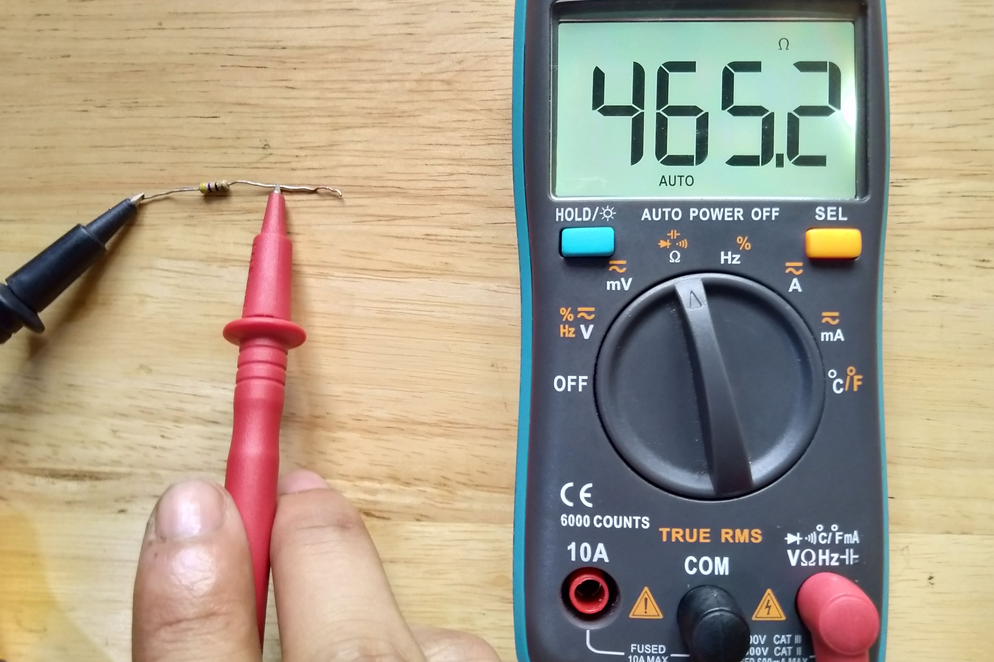
Aside from diodes, one of the most common things to measure with an ohmmeter will of course be a resistor. Unlike a diode, a resistor will block (resist) current for whichever orientation you use your test probe. In the image below, the resistor has a resistance of 465 ohms.
How to Check Continuity
Continuity is not really a value of any sort. However, it is still a valuable test function of a multimeter. The continuity function will test if the current flow of a device/circuit is being disrupted. One of the most common uses of the continuity function is to check if two points of a circuit are connected or not.
To do so, set your rotary switch to the wave/diode symbol, as circled in the image below.

Press the function button until the wave/diode symbol shows up on the display. If you touch two points of a circuit (node) and it makes a sound, that means they're connected. If the multimeter doesn't make a sound, the points are not connected, and you have an open circuit.

As you can see from the image above, one of the wires to the buck converter is not connected. The multimeter doesn't make a sound.

The wire is now connected. The multimeter makes a sound, indicating that the two points are connected.

Another common use of the continuity function is to check if a fuse has blown (resulting in an open circuit) or is still in working condition.
For Those in the Market for a New Multimeter
Multimeters come in different shapes, sizes, and configurations. Some have extra functionalities that make the multimeter more capable. As a beginner, you would want a multimeter that can measure voltage, amperes, ohms, continuity, as well as have features that make it easier for you to read such measurements.
It is highly recommended that you choose a multimeter with a digital display, true RMS, and auto-ranging functionality to make your testing much easier.