Forget breadboards and jumper cables; it’s time to learn how to solder wires and electronics. Join us as we build a basic circuit to demonstrate a range of techniques that you can apply to your own DIY projects and repairs.
What Are We Making?
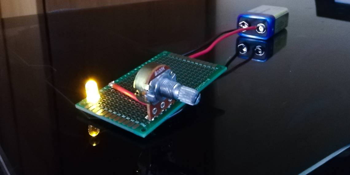
We have chosen an incredibly simple circuit to get started with on this project. A potentiometer is used to control the brightness of an LED that is powered by a 9V battery, giving you the chance to solder a range of components without the challenge of working with a complex web of wires.
What Do You Need?

- 1 x 10kΩ (kiloohms) potentiometer
- 1 x LED
- 1 x 1kΩ resistor
- 1 x 9V battery
- 1 x 9V battery connector harness (Optional)
- 1 x Blank PCB (Optional)
- 22 to 28 AWG PVC or silicone coated wire
The 10kΩ Potentiometer
Potentiometers perform a similar role to resistors, restricting the flow of current in a circuit, only they offer variable control in the form of a rotary knob or slider. This allows us to make our LED brighter or dimmer by increasing or reducing the current that is allowed to flow to it.
The LED
LEDs, or light-emitting diodes, are small electronic components that are able to produce light when they have power passed through them. Our LED has two legs, one for positive and one for negative, making it very easy to work with.
The 1kΩ resistor
Our LED will simply blink out if we allow the full current of the battery to pass through it, and this means that we need a resistor to restrict the current and keep our LED safe. You can tell the value of a resistor by its color band sequence.
The 9V Battery & Battery Connector Harness
Any 9V battery will be enough to power a portable project circuit like this for a long time. We soldered wires directly to our battery, but it is recommended that you use a connector harness to ensure that you don’t damage your battery and create an unpleasant mess.
The Blank PCB
Similar to breadboards, blank PCBs make it easier to create circuits by holding components in place for you. You don’t have to use a blank PCB for this project, but it will make the end result more robust, so we recommend it.
The Circuit Diagram

As you can see from the circuit diagram above, you only need to make a few connections to get this project working. The blank PCB has been left out to make the diagram easier to read, but we will show you how to use this component as we go through the rest of the build.
Step 1: Soldering the 10kΩ Potentiometer

We started by soldering our 10kΩ potentiometer to our blank PCB. The legs fit perfectly through the holes in the PCB, making it very easy to create a secure solder joint for each one, though it is worth being careful to avoid a wonky fit.
Step 2: Soldering the LED

Next up, it’s time to solder the LED to the blank PCB. Simply push the legs through holes in the PCB, soldering them at the base before snipping off the excess wire. We chose to make our LED flush with the PCB, but you could have the LED mounted higher if you prefer.
Step 3: Soldering the 1kΩ Resistor

Our LED wouldn’t last for very long with the full current of the battery flowing through it, but we can solve this with a 1kΩ resistor placed between our LED’s positive leg and the 5V pin of the potentiometer.
To ensure that this stayed nice and neat, we decided to push one end of the resistor through the blank PCB to solder it in place, followed by soldering the other end to the positive leg of the LED.
Step 4: Wiring the 10kΩ Potentiometer to the LED

The potentiometer is the most complex component we are using for this project, with three legs to connect it to our circuit: VIN, VOUT, and GND. VIN is the right-hand leg and is designed to receive a current from a power source, whereas VOUT, the middle leg, is able to output power based on the position of the potentiometer knob/slider. The far-left leg is the GND (ground).
For now, we just need to attach the VOUT and GND legs of our potentiometer to the LED. The VOUT leg needs to be soldered to the resistor, while the GND leg can be soldered directly to the negative leg on the LED.
Step 5: Soldering the Battery Harness

As mentioned earlier in the article, we haven’t used a battery harness for this project, but we recommend adding one to your build to ensure that it is safe. Our blank PCBs come equipped with solder pads around the edges, giving us a secure position to solder our battery/battery harness. We made sure to keep some space between both of the wires, as this will make it easier to connect the battery in the next step.
Step 6: Wiring the Battery Harness to the 10kΩ Potentiometer

This is the final step in this process; we just need to connect our battery harness to the 10kΩ potentiometer we have used. The positive battery connection needs to connect to the right-hand leg of the potentiometer (VIN), while the negative battery connection should be hooked up to the left-hand GND leg of the potentiometer.
Troubleshooting Your Circuit

At this stage, as long as you have a battery attached, you should be able to turn your potentiometer knob to dim and brighten your LED. You can follow the troubleshooting steps below if your project doesn’t work, and it should be nice and easy to solve any problems you might have.
- Test the circuit: Most multimeters come equipped with the ability to test circuits to ensure that they are complete. If you have a tool like this, you can use it to find any poor connections in your circuit that need to be resoldered.
- Test the battery: Flat batteries can make life hard for electronics DIYers, so it’s worth making sure that your battery has power before you try much else. Using a device that has been proven to work is a good way to achieve this.
- Replace components: It’s not always easy to tell whether an LED, resistor, or potentiometer is functional. Replacing or resoldering components in your circuit can both be good ways to fix your project.
Learning How to Solder
Taking on projects like this can be a good way to improve your soldering skills, giving you the chance to work on more complex builds in the future. You can find countless fun and creative electronics projects around the web that will push you to try new things with your favorite hobby.