The Controller Area Network (CAN) bus is a robust and reliable communication protocol that is widely used in various industrial, automotive, and aerospace applications. It is designed for the transmission of data between microcontrollers and devices over a CAN bus network. You may not know this yet, but it’s the thing behind those crazy car dashboard mods you see on social media.
We will walk you through how to build a CAN bus with the MCP2515 CAN module using an Arduino and breadboard. We’ll also go over the Arduino CAN library and demonstrate how to send and receive data over the CAN bus.
What Is a CAN Bus?
The CAN bus is a serial communication protocol that was developed by Bosch in the 1980s. It is widely used in various applications because of its high reliability and robustness. It allows for the transmission of data between devices at high speeds with minimal latency over only two lines: CAN High and CAN Low.
In 1994, the CAN bus became an international standard (ISO 11898) that was designed specifically for rapid serial data exchange between electronic controllers in automotive applications. Check out our comprehensive guide on what a CAN bus is and what role it plays in automotive systems for more detail.
One of the reasons why the CAN bus is so popular is because of its error detection and correction features. The protocol can detect and correct errors in the transmission of data. This makes it ideal for applications where data integrity is critical, such as in industrial automation.
Knowing the MCP2515 CAN Module
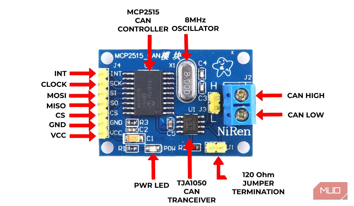
The MCP2515 CAN Bus Controller module is a device that provides exceptional support for the widely used CAN Protocol version 2.0B. This module is ideal for communication at high data rates of up to 1Mbps.
The MCP2515 IC is an independent CAN controller with an SPI Interface that enables communication with a wide range of microcontrollers. The TJA1050 IC, on the other hand, functions as an interface between the MCP2515 CAN controller IC and the physical CAN bus.
For added convenience, there's a jumper that enables you to attach 120 ohm termination, making it even easier to connect your wires to the CAN_H & CAN_L screws for communication with other CAN modules.
|
Feature |
Specification |
|---|---|
|
Transceiver |
TJA1050 |
|
Microcontroller interface |
SPI (allows for Multi CAN bus integration) |
|
Crystal oscillator |
8MHz |
|
Termination |
120Ω |
|
Speed |
1Mbps |
|
Power consumption |
Low-current standby operation |
|
Dimension |
40 x 28mm |
|
Node capacity |
Supports up to 112 nodes |
You can get additional information from the MCP2515 datasheet in case you need this module for a more advanced project.
CAN Message Structure
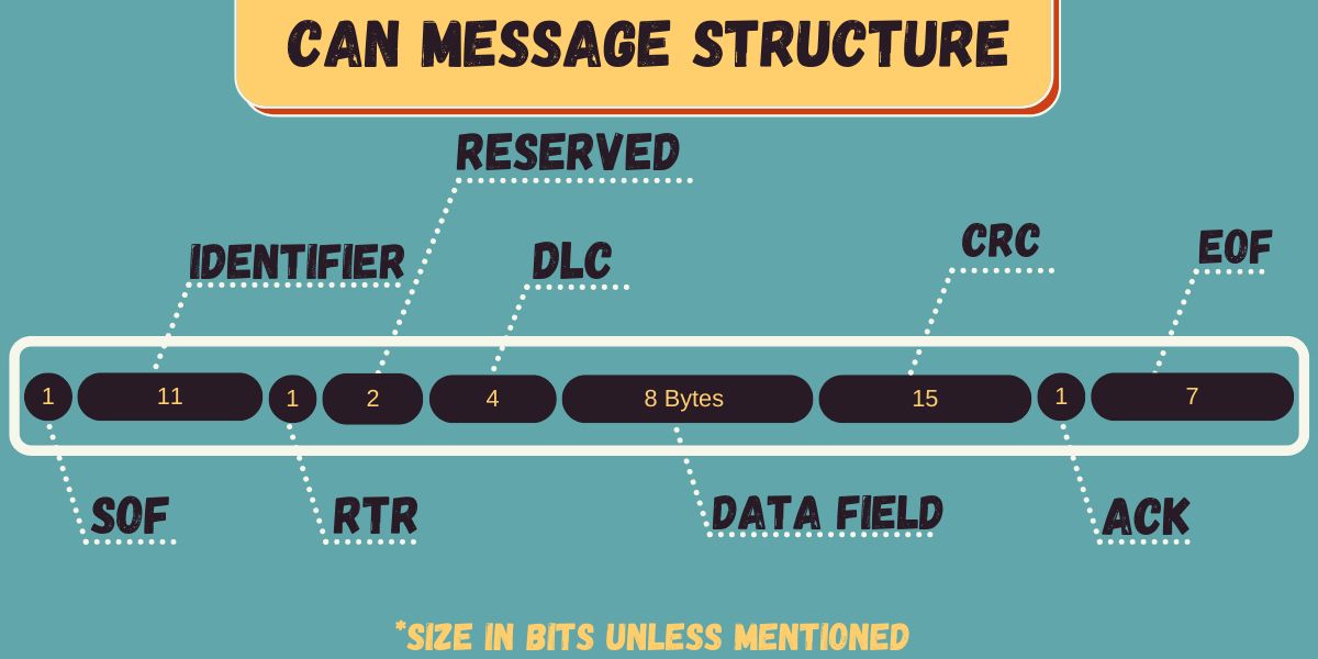
The CAN message structure consists of multiple segments, but the most critical segments for this project are the identifier and data. The identifier, also known as CAN ID or Parameter Group Number (PGN), identifies the devices on the CAN network, and the length of the identifier can be either 11 or 29 bits, depending on the type of CAN protocol used.
Meanwhile, the data represents the actual sensor/control data being transmitted. The data can be anywhere from 0 to 8 bytes long, and the Data Length Code (DLC) indicates the number of data bytes present.
The Arduino MCP2515 CAN Bus Library
This library implements the CAN V2.0B protocol, which can operate at speeds of up to 1Mbps. It provides an SPI interface that can operate at speeds of up to 10MHz while supporting both standard (11-bit) and extended (29-bit) data. What’s more, it comes with two receive buffers, which allow for prioritized message storage.
Initializing the CAN Bus
Here is the setup code you'll need to initialize the CAN bus:
        #include <SPI.h>
#include <mcp2515.h>

MCP2515 mcp2515(10); // Set CS pin

void setup() {
  while (!Serial);
  Serial.begin(9600);
  SPI.begin(); //Begins SPI communication

  mcp2515.reset();
  mcp2515.setBitrate(CAN_500KBPS, MCP_8MHZ);
  mcp2515.setNormalMode();
}
This initializes the MCP2515 with a CAN bit rate of 500Kbps and an oscillator frequency of 8MHz.
MCP2515 CAN Operational Modes
There are three operational modes used with the MCP2515 CAN bus controller:
- setNormalMode(): sets the controller to send and receive messages.
- setLoopbackMode(): sets the controller to send and receive messages, but the messages it sends will also be received by itself.
- setListenOnlyMode(): sets the controller to only receive messages.
These are function calls used to set the operational mode of the MCP2515 CAN bus controller.
mcp2515.setNormalMode();
mcp2515.setLoopbackMode();
mcp2515.setListenOnlyMode();
Sending Data Over the CAN Bus
To send a message over the CAN bus, use the sendMsgBuf() method:
        unsigned char data[] = {0x01, 0x02, 0x03, 0x04};
CAN.sendMsgBuf(0x01, 0, 4, data);
This sends a message with the ID 0x01 and a data payload of {0x01, 0x02, 0x03, 0x04}. The first parameter is the CAN ID, the second is the message priority, the third is the length of the data payload, and the fourth is the data payload itself.
The sendMsgBuf() method returns a value indicating whether the message was sent successfully or not. You can check this value by calling the checkError() method:
        if (CAN.checkError()) {
  Serial.println("Error sending message.");
}
This checks if an error occurred during the transmission of the message and prints an error message if necessary.
Receiving Data From the CAN Bus
To receive a message over the CAN bus, you can use the readMsgBuf() method:
        unsigned char len = 0;
unsigned char buf[8];
unsigned char canID = 0;

if (CAN.checkReceive()) {
  CAN.readMsgBuf(&len, buf);
  canID = CAN.getCanId();
}
This checks if a message is available on the CAN bus and then reads the message into the buf array. The length of the message is stored in the len variable, and the ID of the message is stored in the canID variable.
Once you have received a message, you can process the data payload as needed. For example, you could print the data payload to the serial monitor:
        Serial.print("Received message with ID ");
Serial.print(canID, HEX);
Serial.print(" and data: ");

for (int i = 0; i < len; i++) {
  Serial.print(buf[i], HEX);
  Serial.print(" ");
}

Serial.println();
This prints the ID of the received message and the data payload to the serial monitor.
How to Connect a CAN Bus Transceiver to a Breadboard
To build a CAN bus to connect two devices in this example project, you will need:
- Two microcontrollers (two Arduino Nano boards for this example)
- Two MCP2515 CAN modules
- A breadboard
- Jumper wires
- An I2C 16x2 LCD screen module
- HC-SR04 ultrasonic sensor
For this project example, four libraries are used in the Arduino sketch. There’s the NewPing library, which provides an easy-to-use interface for the Ultrasonic sensor, as well as the SPI library, which facilitates communication between the Arduino board and the MCP2515 CAN bus controller. The LiquidCrystal_I2C library is used for the display module.
Lastly, there’s the mcp2515 library to interface with the MCP2515 chip, allowing us to easily transmit data over the CAN bus network.
Hardware Setup (HC-SR04 Example)
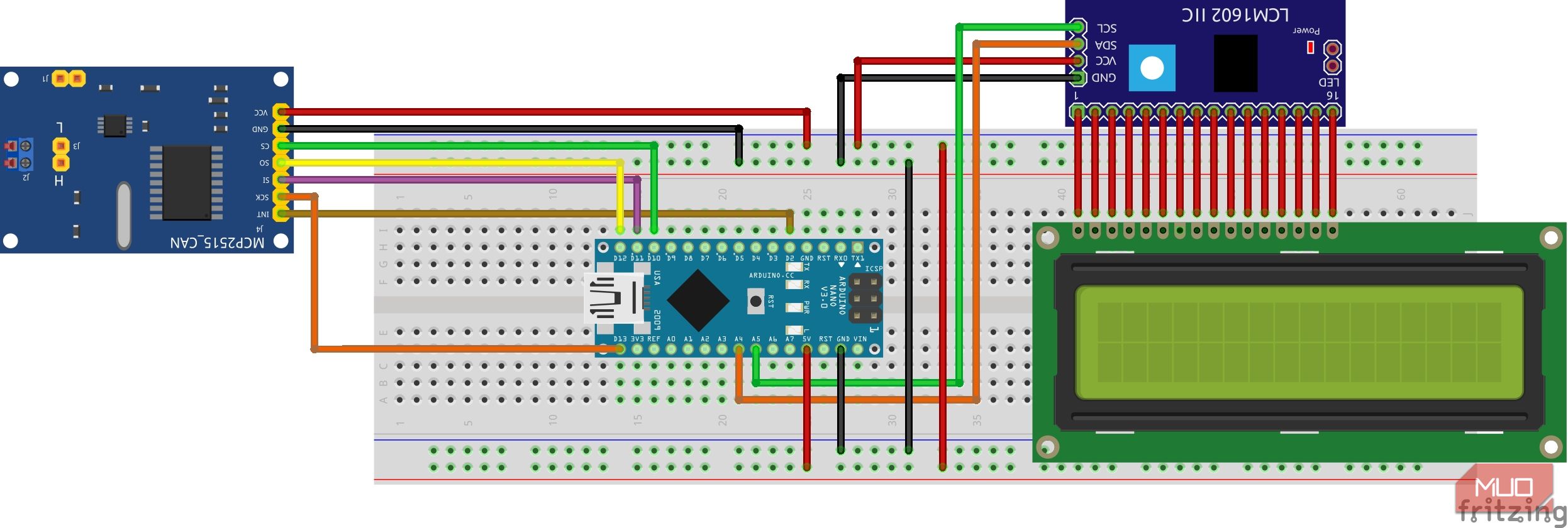
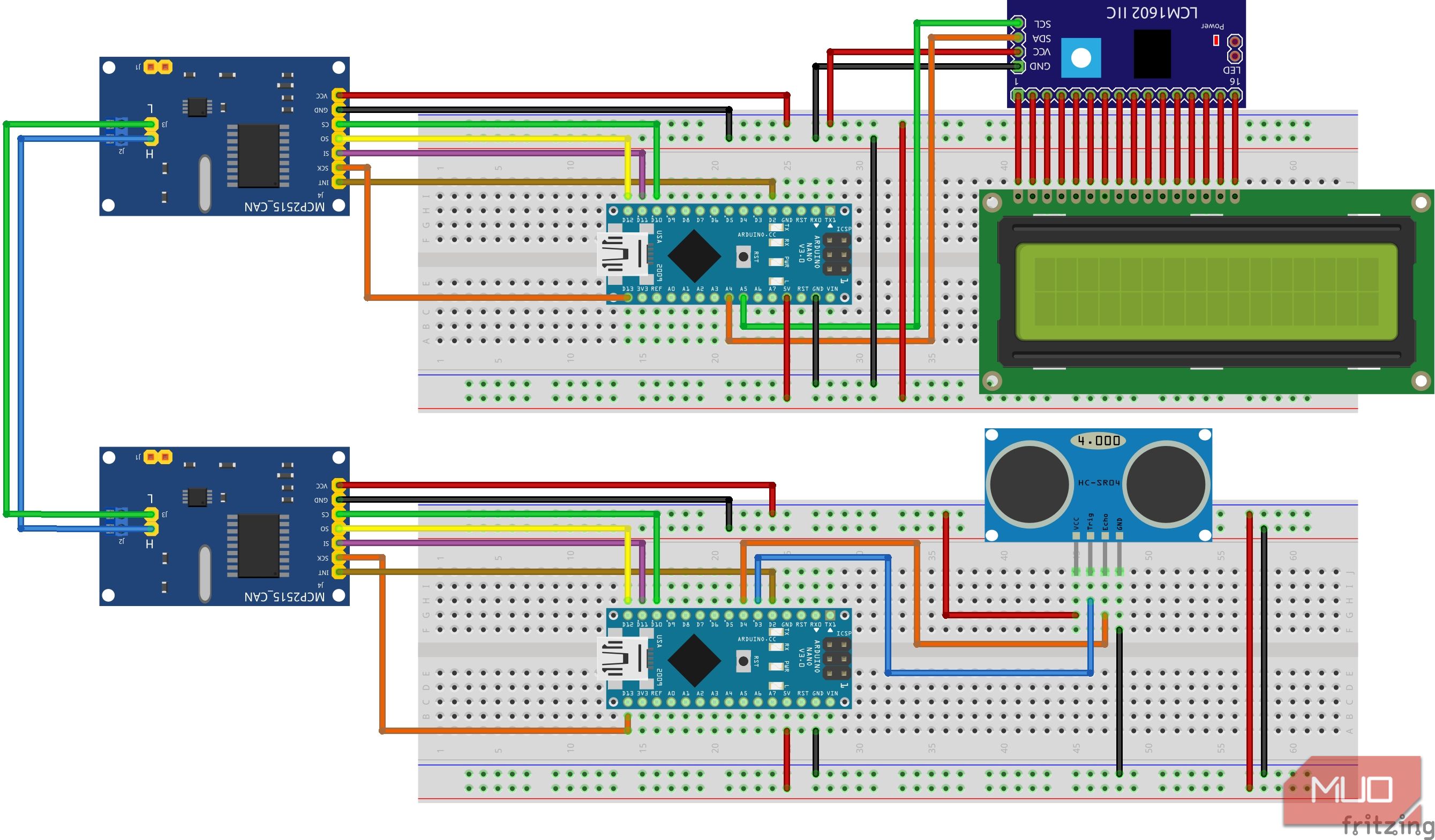
In this project using an HC-SR04 sensor and LCD, one Arduino Nano board will act as a receiver, while the other Arduino will act as a sender. Connect your sender components according to the wiring diagram below:
Here is the diagram for the receiver circuit:
Finally, connect the two nodes together using the CAN_H and CAN_L lines as shown:
When hooking up the modules, it's important to ensure that the power supply voltage is within the specified range and that the CAN H and CAN L pins are properly connected to the bus.
Programming the MCP2515 CAN Bus Module
Note that when programming the MCP2515 module, it is important to use the correct bit rate to ensure successful communication with other CAN devices on the network.
Sender code:
        #include <MCP2515.h>
#include <SPI.h>
#include <NewPing.h>

MCP2515 mcp2515(10);
const byte trigPin = 3;
const byte echoPin = 4;
NewPing sonar(trigPin, echoPin, 200);

struct can_frame canMsg;

void setup() {
  Serial.begin(9600);
  mcp2515.reset();
  mcp2515.setBitrate(CAN_500KBPS, MCP_8MHZ);
  mcp2515.setNormalMode();
}

void loop() {
  unsigned int distance = sonar.ping_cm();
  canMsg.can_id  = 0x036;    //CAN id as 0x036
  canMsg.can_dlc = 8;        //CAN data length as 8
  canMsg.data[0] = distance; //Update humidity value in [0]
  canMsg.data[1] = 0x00;     //Rest all with 0
  canMsg.data[2] = 0x00;
  canMsg.data[3] = 0x00;
  canMsg.data[4] = 0x00;
  canMsg.data[5] = 0x00;
  canMsg.data[6] = 0x00;
  canMsg.data[7] = 0x00;

  mcp2515.sendMessage(&canMsg);//Sends the CAN message
  delay(100);
}
Receiver code:
        #include <mcp2515.h>
#include <SPI.h>
#include <LiquidCrystal_I2C.h>

MCP2515 mcp2515(10);
LiquidCrystal_I2C lcd(0x27,16,2);
struct can_frame canMsg;

void setup() {
  Serial.begin(9600);

  mcp2515.reset();
  mcp2515.setBitrate(CAN_500KBPS, MCP_8MHZ);
  mcp2515.setNormalMode();
  lcd.init();
  lcd.backlight();
  lcd.setCursor(0, 0);
  lcd.print("MUO CAN TUTORIAL");
  delay(3000);
  lcd.clear();
}

void loop() {
  if (mcp2515.readMessage(&canMsg) == MCP2515::ERROR_OK) // To receive data
   {
     int distance = canMsg.data[0];
     lcd.setCursor(0,0);
     lcd.print("Distance: ");
     lcd.print(distance);
     lcd.print("cm ");
   }
}
Take Your Arduino Projects to the Next Level
The combination of the CAN bus and Arduino provides a powerful platform for building or learning sophisticated communication networks used in various applications. While it may seem to be a steep learning curve, having your own setup on a breadboard is a pretty handy way to learn the ropes of using a CAN bus network in complex DIY projects.

