You can buy both mechanical and solid-state relay modules. However, solid-state relays are newer and cost a bit more than the traditional relay switch modules that you might already be using in your DIY smart switches or home automation projects.
In this guide, we will build a solid-state relay from just a few readily available components. You can use these DIY solid-state relays in a production environment and in your home automation or smart switch projects.
Solid-State Relay vs Mechanical Relay: A Quick Comparison
Unlike mechanical relay switches, a solid-state relay has no moving parts. It’s akin to comparing a mechanical hard drive and a solid-state drive, which is way faster and power efficient.
Similarly, a solid-state relay (SSR) works faster and does not consume any power when not in use or switched off. It works or switches on when the trigger voltage is provided by the connected MCU. Most importantly, a solid-state relay occupies a lesser footprint and does not make any clicking noise when triggered.
An SSR can also be used for inductive load switching. However, you must add a snubber circuit to the SSR to prevent damage to the TRIAC (triode for alternating current). This may not be required in some TRIACS, such as the BTA16.
Also, building a solid-state relay is cheaper than buying one or building a mechanical relay module. We have built a few and have been using them in a production environment for the past few months. They work reliably smoother with no issues to date.
Building an AC Solid State Relay Using a TRIAC
You can choose to build a single-channel, dual-channel, or multichannel solid-state relay based on your requirements. To build a single-channel solid-state relay, you will need the following components:
- 220 ohm ¼ watt resistor
- 1K ¼ watt resistor
- BT136 or similar TRIAC
- MOC3021 optocoupler
- Screw terminal
- Two-pin male berg strip connector
- General-purpose PCB
- 6-pin IC base (optional)
- Heat sink (optional but recommended for driving heavier loads)
- LED (optional)
- Soldering iron and solder
You will also need to learn how to solder, if you've never done it before, for building this DIY solid-state relay module.
Step 1: Solder the Components on the PCB
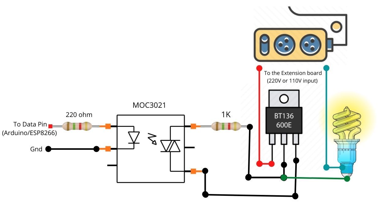
Get the general-purpose PCB board and connect all the components as shown in the following diagram.

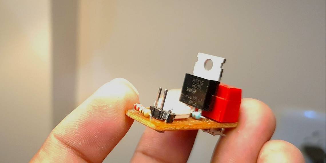
It should look like this after assembling and soldering the required components on the board.

Step 2: Test the Solid-State Relay
To test the DIY solid-state relay, you need a few wires and a 3.3V or 5V power supply. You can use any 3.3V battery or an MCU, such as a NodeMCU, D1 Mini, Arduino Uno, etc., to supply the trigger voltage required for testing the solid-state relay switch.
Testing the solid-state relay and installation involves dealing with a 110V-240V AC power supply. Please proceed only if you know what you are doing. This could be lethal if not done carefully.
- Get an extension board and make sure it is not plugged into or connected to an AC socket.
- Get an AC appliance, such as a fan or bulb.
- Take two wires and connect them to your AC load, e.g. a fan or bulb.
- Connect one of the wires connected to the AC load to the solid-state relay’s screw terminal (T1).
-
Take one more wire, and connect one end to the solid-state relay screw terminal (T2) and the other to the extension board’s socket. It should look like the following diagram. Make sure the connections are secure to avoid short circuits.
- Now connect the two terminals of the 3.3V battery or MCU’s 3.3V and GND terminals to the input pins of the solid-state relay as shown in the diagram. If you are using an MCU, make use of DuPont wires. Also, ensure the polarity is correct, as shown in the diagram.
- Plug the extension board into the AC switch and turn it on.
- The load should switch on. If you disconnect the 3.3V supply from the input terminals of the solid-state relay, the load should switch off.

Solid-State Relay Working
When a 3.3V or trigger voltage is supplied to the solid-state relay, the internal LED or IR LED in the optocoupler turns on and starts emitting light to the optical sensor connected to pin 4 and pin 6.
As a result, the resistance between pin 4 and pin 6 goes low, which triggers the TRIAC and switches on the connected AC load. The optocoupler helps to separate the high-voltage and low-voltage circuits, keeping the Arduino or MCU safe from any interference or damage.
Step 3: Pair the Solid State Relay with Arduino or ESP8266
You may now connect the solid-state relay to an Arduino or other MCU. Instead of three jumper wires for a mechanical relay, you only need two for the SSR: one for the input signal (3.3V) and another for ground (GND).
Based on the load, you can choose higher load-bearing TRIACs, such as the BTA16, with a heat sink to build solid-state relays for heavy loads (2000W or more). Remember to use a snubber circuit if you are going to use the SSR for inductive load switching, such as for a motor or pump.
Use DIY Solid-State Relays to Build Smart Switches
You can use these solid-state relay modules in your smart home projects. You can design ESP12-powered smart switch modules with the integrated solid-state relay using the electronics sketching tool Fritzing. Once designed, you can get the PCB printed from a PCB prototyping/manufacturing service provider or just keep using general-purpose PCBs.
You can use this relay to build a smart motion-sensing light switch or Wi-Fi switches and install them in your home or office. Smart devices can help you reduce energy waste to a significant extent besides being convenient to use. Further, you may also set up a Home Assistant server on Raspberry Pi to add automation.
Replace Mechanical Relays With Solid-State Relays
Now that you have learned to build solid-state relays, you can replace your mechanical relays with an SSR for efficient switching and avoid clicking noises. With a lesser footprint when compared to mechanical relays, you can design and build prototypes or smart switches in much smaller 3D printed cases for your smart home project.