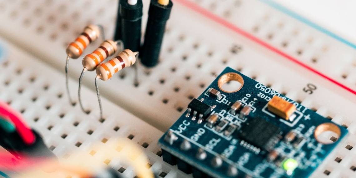
Breadboards simplify electronic circuits, giving enthusiasts and professionals the tools they need to create prototypes and test circuits easily. But how does a breadboard work? Let's look at the inside of a breadboard and build our own basic circuit in the process.
How Does a Breadboard Work?
To learn how a breadboard works, you'll need to understand its parts, what they do, and how the connections work inside. So, let's dive in so that you can figure out how to use a breadboard all by yourself.
Inside an Electronics Breadboard
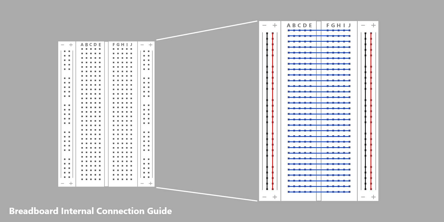
The outer appearance of an electronics breadboard can be a little confusing at first. The small connector holes on the top of a breadboard come in two different varieties: power rails and terminals. Two power rails run up each side of the breadboard as columns, one for positive and one for negative, and each point along these columns is connected.
Terminals are a little different. Rather than running up the breadboard as columns, they run across it as rows. There is usually a gap in the middle of these rows that aren't connected, effectively doubling the number of available terminal rails.
How to Use a Breadboard's Power Rails
As their name suggests, power rails are generally used to connect the breadboard to a power supply. This can be a battery, USB cable, or any other power supply suitable for the components you are working with.
Power rails are easy to use, but they come with some limitations. As the whole power rail is connected, most breadboards can only use two separate power supplies, creating a challenge for complex projects. Therefore, it's best to stick to a single power supply for the first breadboard project you start on. This means that you only have to worry about two connections.
Building a Simple Electronics Circuit With a Breadboard

Breadboards can host complex circuits with loads of components, but learning with a simple circuit is easier, especially for beginners. We've already shown you how to build a simple circuit with a potentiometer controlling the brightness of an LED without a breadboard, providing a good reference point for our breadboard.

Insert each of the LED's legs into holes in the I terminal column to ensure they are not connected. Follow this by inserting each of the potentiometer's legs into holes on the D column.
Next, it's time to add a resistor with one leg on the F terminal column and the other on the E terminal column (connected to the potentiometer's middle leg). Attach a jumper cable between the resistor and the positive leg of the LED. As the final connection to make before adding the battery, attach a jumper cable between the potentiometer's negative leg and the LED's negative leg.
The potentiometer can be connected directly to the power rails. Attach the positive and negative legs to the positive and negative rails respectively, with jumper cables to make the connection. You can attach the battery in the same fashion, as long as you use the same power rails that were used for the potentiometer.
Get Started With Your Breadboard
Breadboards provide a simple way to create prototype circuits and learn more about electronics. Now that you've learned how a breadboard works, you can get started with your breadboard. Feel free to read more in our comprehensive guide to ensure you have all the necessary information.