The Raspberry Pi Pico microcontroller can be programmed with text-based languages such as C, MicroPython, and CircuitPython. But for those learning to program, block-based coding may be less daunting. Now available for Pico, BIPES (Block based Integrated Platform for Embedded Systems) is an excellent option.
Block-based Coding With BIPES
A block-based coding environment for MicroPython devices, BIPES enables you to build programs by dragging and dropping Scratch-like blocks in a Chrome web interface.
In this guide, you will use BIPES to create a simple block-based program for a Raspberry Pi Pico to control the color of a RGB LED mood light. Three rotary potentiometers are used to adjust the red, green, and blue components – the additive primary colors of light. So you can learn a bit of physics in the process.
1. Building the Multicolor Mood Light
To build the mood light, you will need a selection of standard electronic components.
What you’ll need:
- Raspberry Pi Pico with soldered male pin headers
- 800-point breadboard (or 2x linked 400-point breadboards)
- RGB LED
- 3x 330-ohm resistors
- 3x rotary potentiometers
- Male-to-male (M2M) jumper wires
Note: If you don’t fancy soldering male pin headers to your Raspberry Pi Pico, it’s possible to buy a Pico with headers already attached.
Before wiring everything up, take a look at the underside of the Pico to see the pin labels.

On the top of the Pico, you can also see how the physical pin numbering works, from 1 to 40, counter-clockwise from the left of the micro-USB port.

You can also view a diagram of the Pico’s pinout in the Device tab of the BIPES web interface that we'll be using.
On the breadboard, insert the Pico’s male pin headers into the holes at one end. Push it down firmly to ensure good connections – it should fit snugly.
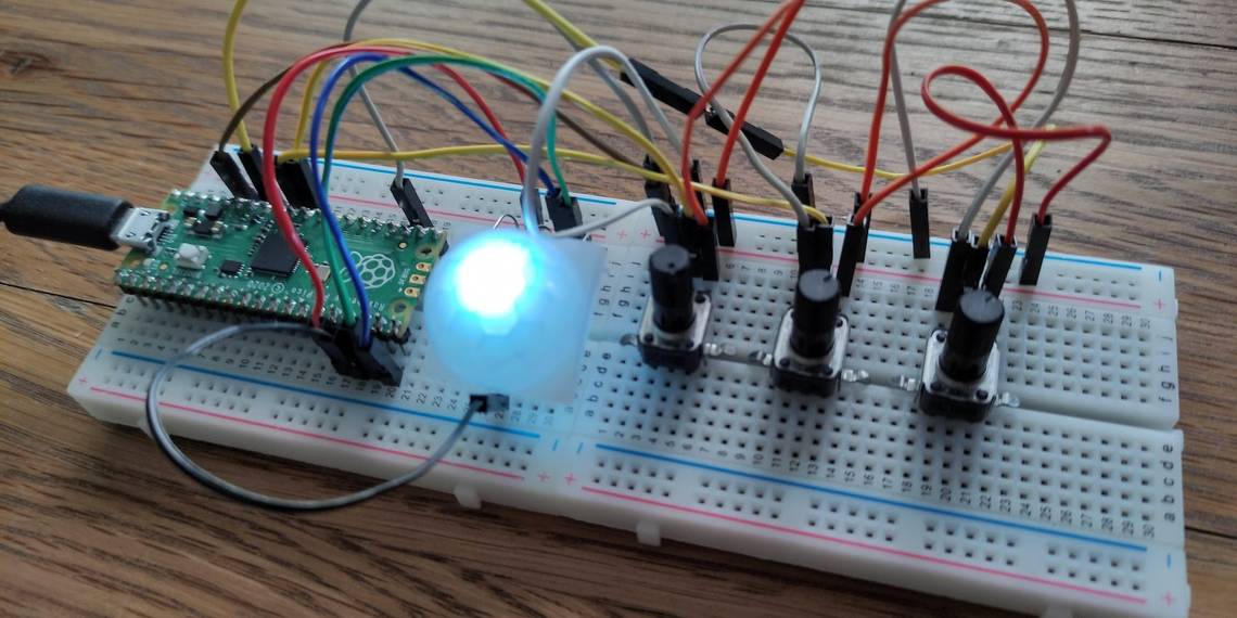
Now connect your RGB LED using four jumper wires, as in the diagram below. The longer leg is connected to a GND (ground) pin, while the others are wired – via resistors – to pins GP13, GP14, and GP15 for the red, green, and blue colors.
Note: we're using a common-cathode RGB LED, so are wiring its long pin to ground. If yours is a common-anode type, you'll need to wire it to 3V3 instead.

Next, wire up the three rotary potentiometers. You’ll need a full-size 800-point breadboard to fit them on. Alternatively, you can use two 400-point ones.
Each potentiometer has three pins. The outer ones are connected to 3V3 power and GND, while the middle pin is wired to one of the Pico’s ADC input pins. This enables its analog signal to be read and converted into a number from 0 to 65535. In our example, we're using ADC0/GP26 for the potentiometer controlling the red component, ADC1/GP27 for green, and ADC2/GP28 for blue.
Finally, connect your Pico to a computer using a micro-USB to USB lead.
2. Programming the Mood Light
For BIPES block-based coding to work, you’ll need to install MicroPython on your Pico (if you haven't done so already). This process involves four simple steps:
- Download MicroPython for Raspberry Pi Pico from the Raspberry Pi website
- Connect the Pico to your computer via its micro-USB socket while holding the BOOTSEL button
- Wait for the Pico to appear as an external drive
- Drag and drop the .uf2 MicroPython file to copy it to the Pi Pico; it will automatically reboot
Now, on the connected computer, open the Google Chrome web browser. To allow BIPES to communicate with the Pico via USB without the need for additional software, you need to enable an experimental feature in Chrome. Enter chrome://flags/ in the address bar and enable the option Experimental Web Platform features.

Go to https://bipes.net.br/beta2serial/ui/ to start coding with BIPES. In the Target device drop-down menu, select Raspberry Pi Pico.
To connect to the Pico, select the Console tab and click Connect (Web Serial). In the dialog, select the Board in FS mode option and then click Connect.

Select the Blocks tab to start creating your block-based program. From the Functions category in the left panel, drag the topmost to do something block into the main code area.
This is equivalent to defining a function in MicroPython. Name it red, as this first function will read your potentiometer to adjust the red value of the RGB LED.
Select the Variables category in the left panel and Create variable. Name it pot1. Drag a set pot1 to block into the middle of your red function block.
From the Machine > In/Out Pins category, drag a Read RPI Pico ADC Input block next to your set pot1 to block in the function. From its pin drop-down menu, select Pin 26 / ADC0 / GP26.

From the Machine > In/Out Pins category, drag a PWM block and place it under the set pot1 block. Select Pin 17 / GP13 from its pin drop-down.
From the Variables category, drag a pot1 block to replace 50 in the Duty section of the PWM block. You now have a function to read a potentiometer and adjust the red component of the RGB LED accordingly. Replicate this for the green and blue components.

Right-click the function block and select Duplicate to copy the entire function. Rename it green and change the pin values to Pin 27 / ADC1 / GP27 and Pin 19 / GP14. Create a new pot2 variable and drag it into the Duty field. Use the drop-down to change the set pot1 to block to set pot2 to.

Duplicate the function again, rename it blue, and change the names and settings accordingly. The pin values are Pin 28 / ADC2 / GP28 and Pin 20 / GP15. The variable is pot3.

Finally, create an infinite loop to run all three functions. From the Loops category, drag a repeat while block to the code area. From the Logic category, drag a true block and attach it. Then, from Functions, drag red, green, and blue blocks into the loop.

3. Test the Mood Light
The program is now complete, so it's time to run it and try out our mood light. Click on the Console tab and select Run block based program.
Now try turning each potentiometer to adjust the red, green, and blue components of the light. You can create countless shades.

Program Raspberry Pi Pico with Block-Based Coding: Success
You have explored how to program your Raspberry Pi Pico using block-based coding with the BIPES web interface in Google Chrome.
In the process, you have also created a multicolor mood light. To diffuse its light, try placing a translucent plastic cover over it – we used one from a PIR sensor.