A breadboard allows you to create circuits without having to solder anything. It is a great tool to experiment with electronics, but it can be intimidating. Having a project to build can help you stay motivated while you learn.
There are several simple games that make great Raspberry Pi beginner projects. An easy one to get you started is the game Simon. Simon is a memory game in which a series of lights flash in random order, and the player must remember the sequence. As the player progresses, the length of the sequence grows.
Required Components
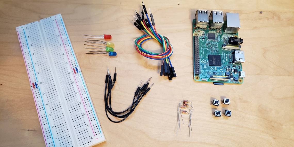
To get started, you will need the following things:
- A Raspberry Pi
- A microSD card flashed with Raspbian OS
- 4 x LEDs of different colors
- 4 x resistors (anything from 220 Ohm to 1 Kilo-Ohm)
- 4 x buttons
- 1 x breadboard
- Jumper cables for connecting everything up
You can use any Raspberry Pi for this project, but the Pi Zero models do not connect to breadboards as easily without some soldering. Whichever model you use, you will also need a power source, monitor, keyboard, and mouse.
If you have never set up a Raspberry Pi before, you can learn how to get everything ready for this tutorial in the Raspberry Pi beginner guide.
You'll be writing Python code in this tutorial, and you can use any text editor to write it, but you might find a code editor easier. There are several already installed on the Raspberry Pi OS, and Thonny is designed to be easy for beginners. Whichever one you use, you'll need to be able to save and run your code to follow this tutorial.
Getting Started With a Breadboard
If you have never used a breadboard before, you may want to start by reading a breadboard tutorial. Understanding how a breadboard works will help you understand how to create circuits.
The Raspberry Pi has two rows of general-purpose input/output (GPIO) pins. These pins allow you to connect components to your Raspberry Pi. Some pins send information, others provide power, and some ground your electronics.

We will begin by adding a LED light to our breadboard. If you have never worked with LED lights on a breadboard before, you might want to read a tutorial that will explain how it works in more depth.
Begin by connecting a GPIO pin to your board. It doesn't matter which pin, as long as it is a GPIO pin and not a power or ground pin. Above is a chart of the GPIO pins, which will help you determine which pin to use. This tutorial uses pin number 18, which is also labeled GPIO 24.
The pin will supply some power to the breadboard and allow the Raspberry Pi to communicate with components on the board. Then connect pin number 6 on the Pi to the ground rail of the breadboard. This will ground the board and allow us to create circuits.

The power coming from the Raspberry is too high to connect the LED directly. Using a resistor brings the power level down and prevents the LED from burning out. Connect one side of the resistor to the same line the GPIO pin is plugged into and the end into the other side of the breadboard. Then place the positive side of the LED after the resistor. The negative end of the LED can be connected directly to the negative rail. The end result should look like the diagram above. Check your wiring thoroughly and turn your Pi on. The LED should light up.
Now, you've made a circuit using your Raspberry Pi that you can control using code.
Using Python Code to Control LEDs
This tutorial takes you through the code in steps, but if you want to refer to the finished code at any time, it's available on Pastebin.
Right now, the power is going to the LED, but we want to control when it turns on and off. The following Python code will allow us to talk to the board.
import RPi.GPIO as GPIO
GPIO.setmode(GPIO.BOARD)
GPIO.setwarnings(False)

red = 18
GPIO.setup(red, GPIO.OUT)
GPIO.output(red, GPIO.LOW)
The first few lines set things up. The Raspberry Pi GPIO library is imported. The as GPIO just lets us refer to RPi.GPIO as GPIO to save a bit of typing. The GPIO pin mode is set to BOARD. You do not have to use this setting, but it can be easier to refer to the pins by their order in the GPIO rows.
Finally, we set warnings to false. This will stop unnecessary warnings.
The next three lines control the LED. The red LED is attached to GPIO pin 18. Instead of remembering that, the variable red will store the location. Next, GPIO.setup tells our program that it is sending information out to the red pin. Finally, we set the GPIO.output on the red pin to low. When you run this program, the light will turn off. To turn it back on, switch GPIO.LOW to GPIO.HIGH, and run the program again.
Save the code, and click run to see it in action. If there is no run button in your code editor, save it and run python myfilename.py in the terminal window. You'll need to navigate to the same directory as your new Python file first. Check the Raspberry Pi cheat sheet if you aren't sure how.
Adding More Than One LED
To create the game Simon, we need four lights of different colors. The same steps that you used to set up the red LED can be used to set up the other three. Your wiring should look like the diagram below:

Your code should look like this:
import RPi.GPIO as GPIO
GPIO.setmode(GPIO.BOARD)
GPIO.setwarnings(False)

red = 18
yellow = 22
green = 24
blue = 26
GPIO.setup(red, GPIO.OUT)
GPIO.setup(yellow, GPIO.OUT)
GPIO.setup(green, GPIO.OUT)
GPIO.setup(blue, GPIO.OUT)
GPIO.output(red, GPIO.HIGH)
GPIO.output(yellow, GPIO.HIGH)
GPIO.output(green, GPIO.HIGH)
GPIO.output(blue, GPIO.HIGH)
Once you have tested the LEDs, set the GPIO.output to GPIO.LOW to turn each one off again.
Although the color of the wires that you use does not matter, try to use colors that have meaning to you to help you read the board easier. For example, black wires are often used for ground wires. In this circuit, you might want to match the color of the wire to the color of the LED light.
Controlling LEDs With Buttons
Begin by adding a button to your board. The button will need to be connected to both the ground and a GPIO pin. The circuit should look something like this:

To make the button control an LED, we need to add to our code. Setting up the button is similar to setting up an LED, except that the GPIO pin is set to be an input, not an output. This code also sets up the internal pull-up resistor on the Pi, which is needed to make the button behave correctly.
GPIO.setup(32, GPIO.IN, pull_up_down=GPIO.PUD_UP)
Now we need code that checks to see if the button has been pressed.
game = True

while game:
    redButtonState = GPIO.input(32)
    if redButtonState == 0:
        GPIO.output(red, GPIO.HIGH)
        time.sleep(1)
        GPIO.output(red, GPIO.LOW)
We want our program to keep checking if a button is pressed, so we use a while loop. Because the loop will never be false, it keeps running and checking the button until we end the program manually by pressing the stop button or using the keyboard shortcut Ctrl + c.
Next, to make it easier to reference the input our button GPIO pin is sending us, we save that information in the variable redButtonState. If our button input changes to 0, we know the button was pressed.
If the button is pressed, the red LED will turn on. Then, after a second, the LED will turn off. To time this, we use the time.sleep(1) function. To make this work, you will need to import the time library at the top of your script.
Once one button is working, you can add three more, one for each LED. Your code should look like this:
import random
import time

import RPi.GPIO as GPIO
GPIO.setmode (GPIO.BOARD)
GPIO.setwarnings(False)

red = 18
yellow = 22
green = 24
blue = 26
GPIO.setup(red, GPIO.OUT)
GPIO.setup(yellow, GPIO.OUT)
GPIO.setup(green, GPIO.OUT)
GPIO.setup(blue, GPIO.OUT)

GPIO.setup(32, GPIO.IN, pull_up_down=GPIO.PUD_UP)
GPIO.setup(36, GPIO.IN, pull_up_down=GPIO.PUD_UP)
GPIO.setup(38, GPIO.IN, pull_up_down=GPIO.PUD_UP)
GPIO.setup(40, GPIO.IN, pull_up_down=GPIO.PUD_UP)
game = True
while game:
    redButtonState = GPIO.input(32)
    if redButtonState == 0:
        GPIO.output(red, GPIO.HIGH)
        time.sleep(1)
        GPIO.output(red, GPIO.LOW)

    yellowButtonState = GPIO.input(36)
    if yellowButtonState == 0:
        GPIO.output(yellow, GPIO.HIGH)
        time.sleep(1)
        GPIO.output(yellow, GPIO.LOW)

    greenButtonState = GPIO.input(38)
    if greenButtonState == 0:
        GPIO.output(green, GPIO.HIGH)
        time.sleep(1)
        GPIO.output(green, GPIO.LOW)

    blueButtonState = GPIO.input(40)
    if blueButtonState == 0:
        GPIO.output(blue, GPIO.HIGH)
        time.sleep(1)
        GPIO.output(blue, GPIO.LOW)
Your board should look something like this:

All of the electronics are now in place. If you have any problems, check through your code for any mistakes. Remember, you can download the full code from Pastebin if you get stuck!
Creating the Game
This project has already covered all of the basics you need to know to start using a breadboard. But turning these skills into a game will really showcase what you can do!
In Simon, a player sees a series of lights flash and has to remember the pattern. It starts easily with only one light. Each level adds a random light to the pattern to make the game harder.
Creating the Pattern
This step is fairly simple. One array will hold our light pattern. A second array will store the GPIO pins for our lights. Every game loop, a new random light will be added to the end of the pattern array. We use the random.randint() function to choose a number between 0 and 3, representing the 4 LEDs.
pattern = []
lights = [red, yellow, green, blue]

while game:
   pattern.append(random.randint(0,3))
Next, we have to light up the lights to show the pattern.
        while game:
   pattern.append(random.randint(0,3))

   for x in pattern:
       GPIO.output(lights[x], GPIO.HIGH)
       time.sleep(1)
       GPIO.output(lights[x], GPIO.LOW)
       time.sleep(0.5)
It is important to pause between two lights. It makes it easier to see if the same light is used back-to-back in the pattern.
Getting Player Input
Next, the game has to wait for the player to guess the order of the lights. The program has to both check each light in the pattern and wait for the player to press a button. This requires nested loops:
for x in pattern:

   waitingForInput = True

   while waitingForInput:
     redButtonState = GPIO.input(32)
     yellowButtonState = GPIO.input(36)
     greenButtonState = GPIO.input(38)
     blueButtonState = GPIO.input(40)

     if redButtonState == 0:
         GPIO.output(red, GPIO.HIGH)
         waitingForInput = False
         time.sleep(1)
         GPIO.output(red, GPIO.LOW)

     if yellowButtonState == 0:
         GPIO.output(yellow, GPIO.HIGH)
         waitingForInput = False
         time.sleep(1)
         GPIO.output(yellow, GPIO.LOW)

     if greenButtonState == 0:
         GPIO.output(green, GPIO.HIGH)
         waitingForInput = False
         time.sleep(1)
         GPIO.output(green, GPIO.LOW)

     if blueButtonState == 0:
         GPIO.output(blue, GPIO.HIGH)
         waitingForInput = False
         time.sleep(1)
         GPIO.output(blue, GPIO.LOW)
Most of the code above is reusing the code we wrote to test the buttons.
Check the Player's Input
From here, it is pretty easy to check if the player has entered the right pattern. Every time they press a button, the game can check to see if that was the correct button. To do this, add another if statement to each button input:
if redButtonState == 0:
   GPIO.output(red, GPIO.HIGH)
   waitingForInput = False
   if x != 0:
       game = False
   time.sleep(1)
   GPIO.output(red, GPIO.LOW)
The variable x from our for loop has the number of the next light. The red LED light is in the first position, or number 0. If the player pressed the red LED button when we have a 0 in our pattern, they are right! If not, they lose the game. Setting the variable game to false will stop our game loop and end the program.
Congratulations! You Built a Game From Scratch!
Creating a game added much more code to this project than just adding LEDs and buttons. Working towards a final project that you can show your friends and family can help keep you motivated.
This game is fairly simple. Challenge yourself to improve upon the basic design. Perhaps the lights could flash if the player loses. Maybe you want to challenge yourself to add sounds to the game. Your imagination is the only limit!
Okay, that and the hardware you have to hand.