There are countless home automation products on the market today, but what if you want to take a DIY approach to create your own smart home? This can be achieved with a relay, Arduino, and a button or sensor; you just need to do some learning to get started.
This guide covers mains voltage electricals. Working with high-voltage electricity is dangerous without the right precautions. You must make sure that your devices are unplugged when you work on them, as well as having an understanding of electricity and basic circuits to stay safe.
DIY Home Electrical Automation

The approach to home automation we are tackling in this project is quite a simple one. It will focus on turning a single electrical device on and off using a relay, Arduino, and a simple push button. It will also take you through some of the other component options to replace the push button and further automate your home.
What Is a Relay?
A relay lies at the heart of this project, acting as an electronic switch that is controlled by an Arduino. As electrical switches, relays open and close based on digital signals received from a computer or microcontroller board. This makes them ideal for DIY home automation, as they work well with Arduinos and other basic boards.
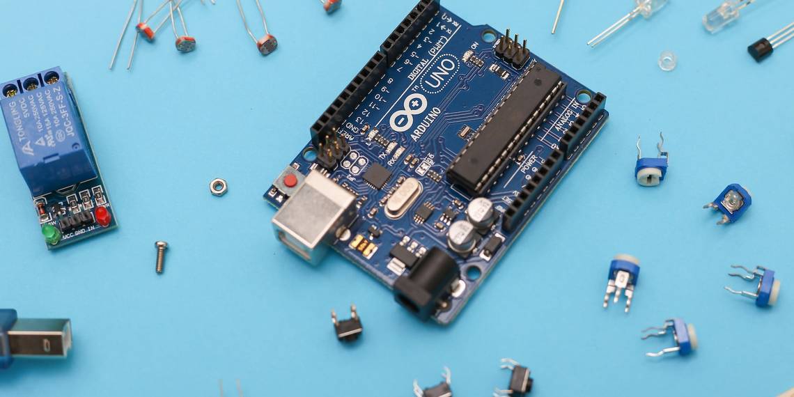
What You Need for This DIY Home Automation Project
You need a few different components to get started with this project. Most of these components are essential to the project, but you can swap out the button for something else if you want to change your control method.
- Any Arduino Microcontroller Board: You can use any Arduino board for this project. We picked an Arduino Pro Micro because they are nice and small, but an Uno would work just as well.
- A 5V Active Low Relay Board: You can find relay board with one, two, four, and eight channels. Choose one that matches the number of electrical devices it needs to control.
- Push Button and 10kΩ Resistor (Optional): Our DIY automation project uses a button to activate the relay, but you can choose from a range of other components that we will explore later.
- An Electronic Device: This final part is the electronic device you want to automate. We picked a lamp for our project, but you can use anything that matches the specifications of your relay.
Step 1: Prepare Your Lamp (or Other Device) for Automation

The first step in this DIY automation process is easy; you just have to prepare your electrical device. This means exposing the positive power wire within its main cable. Of course, though, you have to unplug your device before attempting this.
The lamp we are using already has an inline power switch on its cable. This is ideal, as it means that the lamp is ready for a relay to be installed already, and we just have to remove the switch.

You will have to dig a little deeper if your device doesn’t have a switch like this. Stripping electrical cables isn’t too difficult, but you have to be extremely careful to make sure that the internal wires are still properly insulated by the end.
Step 2: Connect the Relay to Your Electrical Device

Next, it’s time to attach your relay to the cable you just exposed. Start by cutting the cable to make a break in it and stripping the ends of the wires to expose their metal cores.
Most relays have three connection points, but you only need to use two of them: the middle and one of the outer connectors. Push each side of the exposed wires into the connectors on your relay and screw them down tightly. You need a good connection here to make sure your DIY project is safe.
Step 3: Connect the Relay to the Arduino

Your Arduino also needs to connect to your relay, and this requires three connections: VCC, Ground, and Data. Solder the VCC and Ground pins on your Arduino to the respective pins on the relay, followed by connecting one of the Arduino’s digital pins to the Data pin on the relay.
It’s worth keeping in mind that your relay’s pin layout may not be the same as the one in the wiring diagram shown below. Also, relays with more than one channel with have multiple Data pins but only one set of VCC and Ground pins. You can check out our handy soldering beginner's guide to make sure you solder your components correctly.

Step 4: Connect a Push Button to Your Arduino

At this stage, your DIY home automation project may diverge from ours. Our lamp is controlled by a simple push button, enabling the lamp to be turned on from a much greater distance than before. Check out the wiring diagram below.
Alternatively, you could also consider some of the ideas below to control your relay. Whatever you choose, you will need to hook it up to your Arduino and work on some code to get it working properly.
- Real-Time Clocks: RTC modules measure and keep time, much like a regular clock. An RTC could be used to turn on your relay at specific times, automating your electronics based on what the clock says. This DIY aquarium lighting guide shows you how to get started with a real-time clock.
- Movement Sensors: A movement sensor can trigger an array when it detects movement. You can use this to create a motion-sensing electronic device, like a lamp or fan that turns on when you sit at your desk.
- Light Sensors: These are perfect for lamps and other light sources, enabling you to turn on your lights when it starts to get dark inside your home. Of course, you will need to code your sensor so that it doesn’t get triggered by the electric light itself.
- Other Sensors: You can choose just about any sensor to control your relay, as long as you can write the code for it.
Step 5: Load Some Code Onto Your Arduino
As the last step in this process, it’s time to load some code onto your Arduino. You may need to adapt this code to match the components you use, but it is simple and should be easy to edit to meet your needs.
It starts with some basic variable declarations before initializing the button and relay in the setup() function. This is followed by a loop() function with a couple of if statements to determine the state of the button and the relay.
        int buttonState = 0;  //Create a button state variable to read the button's position
int relayState = 0; //Create a relay state variable to set the relay's position


void setup() {
 pinMode(15, OUTPUT); //Initialize the relay pin as an output (digital pin 15 in our case)
 pinMode(10, INPUT); //Initialize the button pin as an input (digital pin 10 in our case)
}


void loop() {
 buttonState = digitalRead(10); //Read the state of the push button

 if (buttonState == HIGH) { //If statement to check if the push button is open or closed

   if (relayState == 0) { //Check the relay state and change it to the opposite when the button is pressed

     relayState = 1;

   } else {

     relayState = 0;

   }

 }


 if (relayState == 0) { //Check the relay state and activate the relay if it isn't 0

   digitalWrite(15, HIGH); //Activate the relay

 } else {

   digitalWrite(15, LOW);

 }


 delay(1000); //Create a short delay to prevent the light from flashing on and off

}
Getting Started With DIY Home Automation
There are countless home automation products on the market nowadays. You can use devices like this to turn your house into a smart home, but working on your own DIY home automation is a lot more fun.