Pong was the first ever videogame that reached the mass market. For the first time in history, the concept of a "video game" was brought into the family home, thanks to the Atari 2600 - so it's only right that we pay a little homage to this historical gem. Now, you can re-live that (admittedly somewhat boring gameplay) using an Arduino and some common components.
I won't lie - it's unlikely your daughter will be giving up her Nintendo DS, and this isn't going to provide hours of fun for the whole family - but it is an awesome and easy project to improve your Arduino coding. And if you're just getting started, don't forget to check out our beginner's Arduino guide.
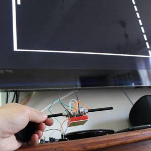
We'll make two basic controllers, and the video will output to your TV through a standard composite video cable.
To take this project to the next level, you could 3D print an enclosure. YouTube user PotentPrintables did just that!
Requirements for Arduino Pong
- 470 ohm resistor x1
- 1k ohm resistor x1
- 10k ohm Potentiometer (twiddly variable resistor) x2
- Arduino x1 (any version)
- RCA plug x1 (if you have more than one, you can hook up sound too. One for the video is a bare minimum)
- Pushbutton switch x1
- 10k ohm resistor x1

You'll also to download the TV Out Arduino library from here - get the TVoutBeta1.zip, the latest release. Place the resulting folders all into your /arduino/libraries directory, and restart the Arduino IDE if it's open already.
Testing TV Out
Take your RCA plug and strip the outer layer away. Gather up the shielding, twist and put away to one side. This is your ground. In the center should be another cable with plastic shielding - again, strip this away so you have your signal line.

Solder both the 470 ohm and 1k ohm resistors to the centre signal line of your RCA plug - this provides a sync signal and the actual video signal, combined to produce the analogue video input. The 470 ohm resistor should slot into digital IO pin D07, while the 1k ohm resistor goes to pin D09.
These pins are set by the library we import, so you can't change them. One of your Arduino GND pins should go to the shielding (outside) of the RCA.

Now you can go ahead and load in an example; although both PAL and NTSC are provided, it shouldn't really matter with modern digital TVs - the NTSC demo worked fine for me despite being in the UK. Plug into your TV, and should get a lovely retro 3D cube. Oooooh yeah - are you excited yet? I am.

Test Analogue Potentiometer Inputs
Ok, we've got the TV output working, now let's have a go with the controllers. The wiring of the "pots" is not so critical - each should have 3 pins, and the central one nearly always produces the output signal. Wire that to A0 and A1 (one for each pot). On one of the side pins - it doesn't matter which - wire up +5V. The other pin on the other side should go to ground.
Here I've put them both facing each on single breadboard, because I only have short wires. For a polished product, you'll want to use some old networking cable to give you a bit of distance (so you can actually sit on the sofa to play).

Next, load up one of the basic example sketches that come with the Arduino - the analog input one. This demo will flash the onboard LED faster or slower, depending on the input on A0.
It doesn't test the other A1 pot, but if you've got A0 wired up right then I can't see how you would make a mistake on A1, so let's assume that's all good and move on.
Add a Start Switch
Finally, we'll add a start switch on D02. Refer to the wiring diagram here for how to do that. This switch will be used to start the game when in the menu.

The Pong Code
We're using some code originally written by Lamonica, modified by duboisvb for two players, and updated by myself to use the latest beta version of the TV out library. You can view and download the code from this pastebin.
It's quite long but simple code that shouldn't require any explanation from me. Like most games, it relies upon a game state (menu, in-game, game over), and reads the input values of both controllers and the switch each iteration of the loop. Beyond that are the methods to draw the screen, the ball, the paddles, and the game logic.

Note that the code includes audio output too: I couldn't find any more RCA plugs to test that, but if you have some, then wire the signal pin directly to D11, and you should get some pleasing retro tones.

To be honest, I didn't know Arduino could even do TV out without some immensely complex coding; the TV out library makes it really easy. Even if you're not into retro gaming, using this basic TV out is a great way to utilise existing equipment as a cheap monitor device. You can of course output colour, too.
Do you think you'll have a go at Arduino Pong, or perhaps make your own retro videogame remake? Tell us in the comments if you have!