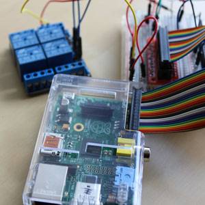
If you though the Arduino was cool, just wait till you get your hands on a Raspberry Pi - these things are amazing. As well as being a fully functional computer, they also have a selection of General Purpose Input/Output pins. Just like an Arduino, we can use these to create electronics projects - and it's surprisingly easy to get started.
Today we'll be connecting up a relay and using it to turn on an LED, but you could just as easily turn on a lamp.
This introduction serves as the first part to a larger home automation project. Christian has already laid the foundations on getting started with a Pi, so I won't be repeating the initial steps here of downloading an OS or plugging in the SD card - I'll assume you have a working Raspian system already set up.
Warning: Although a Raspberry Pi can be used similarly to an Arduino, a little more care is needed. The pins of the Pi operate at 3.3v, whilst the Arduino uses 5v. While it is possible to break an Arduino, it's a lot easier to break a Pi as the pins connect directly to the onboard chip - sending 5v down there may fry it.
Therefore, be very careful about trying to replicate Arduino projects on your Pi - either follow a Pi specific tutorial, or be sure to have a good understanding of basic electronics.
Requirements:
- NPN transistor, such as P2N2222A
- 1k resistor
- Relay; I'm using a 4-relay 5v module which has additional protection circuitry built-in (so no need for extra diodes
- LED and 220 ohm resistor for testing
- Breakout cable
Breakout cable ("Cobbler Kit")
The GPIO pins are situated on the side of the Pi, next to the RCA video out socket.

Although you could technically connect some female ended jumper cables directly to these, they're not labelled in any useful way and you're therefore more likely to break something. Instead, get a breakout cable such as this one from Adafruit, or one of the many cheaper clones on eBay. You may need to solder this as it'll come in kit form.

Although the board side has a notch in it to indicate correct cable placement, the Pi side doesn't. Ensure that the 3v and 5v pins in the far corner of the Pi align with the relevant pins on the board. Of course, if you bought a case that doesn't expose the GPIO header then you're going to need to run with naked Pi, or cut a hole.

Alternatively, you can get a full board that affixes on top of your Pi, and usually comes with a selection of useful components.
Basic Circuit
Set up the circuit as outlined below. I've left out the relay circuitry as this will vary. Use the NO (normally closed) and COM terminals of your relay for your LED or other device.

Use pin 4 from the Raspberry Pi. On my breakout board, it's labelled +GPCLK0; regardless, it's the fourth pin counting from 3V3.

Command line testing
In the following examples, I assume you're logged in over SSH or otherwise as the root user. If not, you'll need to preface some of the commands with sudo for elevated privileges.
First, we need to install WiringPi.
        git clone git://git.drogon.net/wiringPi
 cd wiringPi
 ./build
Assuming that all went well, we should now be able to directly control the GPIO from the command line like this:
gpio -g mode 4 out

            gpio -g write 4 1
The first command is similar to the Arduino's setup function where we're telling the Pi use pin 4 as an output. The next command writes a value of 1 to the pin, which should trigger the transistor, activate the relay, close the circuit for the LED and turn it on.
Awesome. If it doesn't, go back and check your wiring. Does the relay click?
Python
Although Python isn't the only way to communicate with the GPIO pins, it's generally considered the easiest, and it's the most commonly found in existing projects. Unlike C, Python is relatively easy to pick up (here's 5 sites to learn Python).
Begin by installing the following Python extensions:
        apt-get install python-dev
 apt-get install python-rpi.gpio
Now, create a new file called test.py. if you're using a command line, type
nano test.py
Paste or type in the following (also on this pastebin):
        import RPi.GPIO as GPIO
import time
GPIO.setmode(GPIO.BCM)
GPIO.setup(4, GPIO.OUT)
for x in range(0,10):
  time.sleep(5)
  GPIO.output(4,1)
  time.sleep(5)
  GPIO.output(4,0)
This is a very simple Python script which is going to turn the LED (or whatever you have hooked up to your relay) on for 5 seconds, then off for 5 seconds, 10 times. You should be able to understand most of the code. The GPIO.setmode line is simply used to indicate the pin numbering scheme we're going to use.
That's it! To run the code, type:
python test.py

Next week, we'll be elaborating the setup a little and doing some exciting stuff like adding voice control. If you're going to add high voltage electrical items into the relay circuit, you'll want to be sure that you're using an appropriately rated relay on the live wire, and make sure to enclose everything so it's away from the prying fingers of babies, or mum. Seriously though, be safe.
Please post your questions, comments, feedback and haikus into the box below - but bear in mind I will grade you on use of grammar.