Despite sounding like an alcopop, Fritzing is actually an incredible bit of free software you can use to create circuit and component diagrams for use with rapid-protoyping electronics boards such as the fantastic open-source Arduino.
As such, it’s open source too, entirely cross platform and well supported - you can almost guarantee that it can be used on any Arduino project to show you how to wire things together using it.
Having just begun on the path of the Arduino hardware tinkerer myself, I checked it out as way to document any modifications I make to projects I create from tutorials.
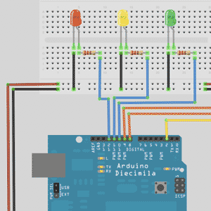
Before I get started, let me show the final diagram I put together in less than 10 minutes. Pretty good huh?

It's quite messy though and very unclear, I know - but that’s because I’m working retroactively - drawing what I actually made rather than designing what to make. If I had used this first, it would have been a whole neater. It’s a modification of one the first projects in the Beginning Arduino book - a traffic light and pedestrian crossing system - to which I added a simple buzzer.
The circuit itself varies very little, but the programming behind it required some major adjustments to allow for simultaneous buzzing and flashing of LEDs at different rates. I’ve uploaded the code portion to paste bin for those of you interested, but it’s not relevant to this review and hopefully I’ll be teaching you the basics of programming the Arduino at a later date if there’s enough interest.
Download
Head on over to the Fritzing download page. It’s an executable that needn’t be installed, so just unzip or mount the .dmg file, then just run the application.
Features
I’ll be concentrating on the prototyping functionality today, but it can also be used for both the electronic schematics, as well as designing a full PCB if you decide you want to make your project more permanent. In fact, they even offer a PCB production service, which costs about $40 for an Arduino shield sized PCB (commonly used to place your own PCB on top of an Arduino for a snug fit).
Basic Controls
This is what you'll see upon first launch:

Drag components out from the toolbox in the top right. Scroll down for micro controllers and you can find an Arduino. The next box down on the sidebar is an inspector. In my case, I'm using two mini-breadboards, so I added them from the toolbox and changed the sizes using the inspector.

Note: To rearrange items on the diagram, drag the component anywhere non-functional - that is, not from one of the pin holes - use the edges. You can also zoom in if you’re finding it hard to grab a non-functional bit of the board.
Next, add some more components and join them all up. Here’s the photo of the actual project I’m trying to document here:

Drag out your first component, in my case a buzzer. To connect the terminals, just drag from one point to another. As you hover over a specific pin on the Arduino, a tooltip will let you check the number.

Since the wiring is a little messy like that, you can then click and drag anywhere on the line to add another point and ‘bend’ the wire around.

Notice that while you’re doing this, it’s also building a circuit diagram schematic on the other screens. Click over to schematic or even PCB view. It doesn’t automatically tidy those up for you - if you need the PCB to be neat and tidy it’s best if you go over and clean it up as you make the circuit. You can drag and drop on either screen just as easily, and make use of the rotate and flip buttons on the bottom left if needed.

If you hold down the CTRL key while clicking on a component, a option menu will appear with various menu items.
CMD-D (Mac) or CTRL-D (Windows) will duplicate the current item - useful if you’re trying to place an array of LEDs.
To move the entire component, just click and drag on the component itself (not the legs). Moving individual legs can be a little tricky, and you may find yourself drawing a connection instead.
Once the legs are correctly placed, you can hold down ALT and drag around the component without affecting it’s pins.

Breadboards to show connected lines will automatically light up in green when something is connected to them.
Overall, it's incredibly easy to use, and the fact that it's free is a testament to the power of the open source community. I hope you get a chance to play with the software and design some of your own circuits too. If you are interested in learning the basics of Arduino programming, including some fundamental electronics in the process - and building up to a complete robot or something equally impressive - do let me know in the comments. I’d love to publish a full 10 part tutorial, but without feedback from you guys it’s difficult to gauge the interest.
Here’s hoping you have a happy hardware hacking weekend!