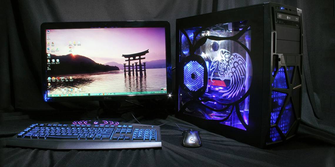
Desktop PC towers have come a long way since the days of gray plastic towers hidden under desks. Alongside cases which fulfill different functions, PC cases have evolved a sense of aesthetics, with glass panels proudly showing off components, and strong futuristic designs taking center stage on any proud geek's desk.

LED installations are becoming ever more common. A simple 12v RGB strip can be bought for as little as $1 per meter and will light up the inside of a case (along with almost anything else) perfectly well.
However, we want to do something a little more special than this! Today we shall use Pixel LEDs to create Wi-Fi controllable case lighting, with custom If This Then That (IFTTT) notifications. This whole system is powered using a spare Molex connector inside the tower, making it totally self contained. Best of all, this whole project costs under $10 to make.
This tutorial is available in video form below, or keep reading for the written version.
Lights With Brains
We will be using individually addressable LEDs for this project. Sometimes known as Neopixels, there are various models to choose from. The LEDs used here are from a WS2812B strip, available for around $4 per meter.
We will be using the NodeMCU board to control them. While you could use any Arduino compatible board with Wi-Fi, the NodeMCU is a favorite of ours as an Arduino killer.
What You Need
- 1 x 5v Pixel LED strip, Neopixel/WS2811/12/12B
- 1 x NodeMCU ($3 on AliExpress)
- 1 x 220-500 Ohm resistor
- 1 x 100-1000 microFarad capacitor
- 1 x Toggle switch or circuit breaker
- 1 x Female Molex connector
- 1 x Breadboard
- 1 x 5v power supply (for testing)
- 1 x Proto-board and wire (for installing the circuit)
- Various hookup wires
- Soldering iron and solder
The only thing in this list which is out of the ordinary here is the Molex connector. Many PC owners these days do not use a CD drive at all in their builds, though power supplies still come with a connection for them. We can use these spare power lines to our advantage. I salvaged my female connector from an old disk drive, though they are available for as little as $0.30.
Build Your Circuit
To avoid unnecessary poking around in our case we will test our setup using an external power supply. Set up your breadboard like this.

If this your first time setting up these kind of LEDs, I would advise looking over our in-depth guide to using these strips with Arduino first.
The switch simply breaks the NodeMCU from the circuit. In this build I will actually be using a simple circuit breaker in place of the switch. Its function is to allow us to isolate the board's VIN pin while it is connected via USB. While the amount of power our LEDs will be drawing is relatively small, it is a good practice to avoid pulling too much power via USB.
Once your breadboard is set up it should look something like this:

In my example, the capacitor and resistor are already on proto-board as it was salvaged from an older project, though the circuit is exactly the same.
Now that we have the hardware set up, let's create our code.
The Brains of the Operation
You will be coding your NodeMCU using the Arduino IDE. For this example, we will set up two modes of operation, a master on/off switch, and a notification signal when an email is received. We will be using Blynk [Broken URL Removed], a web service for Internet of Things devices to communicate with our board.
Make sure you check out our Blynk introductory article if you've never used it before.
In the Blynk app, set up a new project and select NodeMCU as your board. An authorisation code will be sent to your email address registered with Blynk. Add 3 buttons and 3 sliders.

These buttons and sliders should be set to send values to Virtual Pins V0-V5. The "Test" button will test our email notification for now. Label the other two buttons Power and Auto/Manual or something similar, and the three sliders are for Red, Green, and Blue.
Now open the Arduino IDE. You will need the Blynk and FastLED libraries for this project, so make sure you have both installed. If you are just starting out with the Arduino IDE, check out our Arduino beginner's guide.
We will break the code down into chunks here, though if you would prefer to simply download the full code, you can find it on GitHub.
If you decide to do this, be sure to add your own Wi-Fi details, authorization code, and relevant NodeMCU pin and Number of LEDs to the script. If you are just beginning to learn programming I would go through it from scratch in order to learn how every part works. This is one of many ways to get to grips with coding.
Create a new sketch and save it with an appropriate name. Make sure to select the correct board and port from the Tools > Board and Tools > Port menus. Begin by including the relevant Blynk and FastLED name-spaces:
        #define BLYNK_PRINT Serial
#include <ESP8266WiFi.h>
#include <BlynkSimpleEsp8266.h>
#include "FastLED.h"
Next, add some definitions for FastLED:
        //---FastLED definitions and CRGB---
#define LED_PIN 3 // GPIO pin for RGB LEDs.
#define NUM_LEDS 44 // Number of LEDs connected.
#define BRIGHTNESS 64 // Default LED brightness.
#define LED_TYPE WS2812B
#define COLOR_ORDER GRB
CRGB leds[NUM_LEDS];
Next we will declare variables for our RGB values, our Automatic/Manual mode, and our master switch. We also add a value for a base color required by the FastLED preset we will be using later.
        //---variables for our RGB values (0-1023) ---
int r = 500;
int g = 500;
int b = 500;

//---variables for On/Off, and Auto/Manual toggle
int masterSwitch = 1;
int autoMode = 1;

//--- int/byte for automatic hue incrementation---
uint8_t gHue = 0; // rotating "base color" used by many of the patterns
When adding your Blynk details, be sure to fill in your own Wi-Fi details here:
        //---Blynk auth code and wifi details---
char auth[] = "YourAuthCode";//Blynk authorisation
char ssid[] = "YourWifiName";
char pass[] = "YourWifiPassword";
We use our Setup function to add our LEDs to FastLED, and establish communication with Blynk.
        void setup() {
  // power-up safety delay
  delay(3000);
  Serial.begin(9600);

  //--- add the LEDS to FastLED and set the brightness---
  FastLED.addLeds<LED_TYPE, LED_PIN, COLOR_ORDER>(leds, NUM_LEDS).setCorrection(TypicalSMD5050);
  FastLED.setBrightness(BRIGHTNESS);
  #define FRAMES_PER_SECOND 120

  //---start communication with the Blynk server ---
  Blynk.begin(auth, ssid, pass);
}
Use if-statements in your Loop function to do different things depending on what mode you are in.
        void loop() {
  Blynk.run();
  if(masterSwitch == 0) {
    for (int i = 0; i < NUM_LEDS; i++) {
      leds[i] = CRGB::Black;
      FastLED.show();
      delay(30);
    }
  }
  if(autoMode == 0 && masterSwitch == 1) {
    for (int i = 0; i < NUM_LEDS; i++){
      leds[i] = CRGB(r, g, b);
      FastLED.show();
      delay(30);
    }
  }
  if(autoMode == 1 && masterSwitch == 1) {
    fill_rainbow( leds, NUM_LEDS, gHue, 7);
    // send the 'leds' array out to the actual LED strip
    FastLED.show();
    // insert a delay to keep the framerate modest
    FastLED.delay(1000/FRAMES_PER_SECOND);
    EVERY_N_MILLISECONDS(20) {
      gHue++; // slowly cycle the "base color" through the rainbow
    }
  }
}
Now, use the BLYNK_WRITE functions to change these variables depending on what you select in the Blynk app:
        //---Master On/Off---
BLYNK_WRITE(V0) {
  masterSwitch = param.asInt();
}

//--- Red slider value---
BLYNK_WRITE(V1) {
  r = param.asInt();
}

//--- Green slider value---
BLYNK_WRITE(V2) {
  g = param.asInt();
}

//--- Blue slider value---
BLYNK_WRITE(V3) {
  b = param.asInt();
}

//--- Toggle Auto/Manual Mode ---
BLYNK_WRITE(V4) {
  autoMode = param.asInt();
}
Finally, make a function which causes a repeated sequence of red lights to use as your email notification. This is designed to trigger no matter what else is happening, meaning you will always get the notification, even if the lights are currently off.
        //---Email notification light---
BLYNK_WRITE(V5) {
  int g = param.asInt();

  if(g == 1) {
    for(int a = 0; a < 10 ; a++) {
      for (int i = 0; i< NUM_LEDS; i++) {
        leds[i] = CRGB(1023, 0, 0);
        FastLED.show();
        delay(10);
        FastLED.clear();
        delay(10);
      }
    }
  }
}
Once you have this full code in place, use the switch/circuit breaker to isolate the NodeMCU from the circuit, and plug it in via USB. Upload the sketch to the board. Once uploaded, disconnect the USB cable, and connect your 5v power supply. All being well the LED strip should start up in the automatic mode, which is the fill_rainbow mode from FastLED. You can test the notification signal using the test button.

As you can see here, I laid out my LEDs roughly on the side of my case so I knew how many I would need. In my case it was 44, though I use a mini tower, so you may be able to use many more. Just be sure to take into account the power draw of the LEDs you use, and how much your PC's power supply can provide.
Configuring IFTTT
We will be using IFTTT's Gmail integration to trigger our notification sequence. If you've never used IFTTT before, you'll be amazed at the sheer amount of ways you can automate your favorite web apps.
Set up a new applet. For "This", choose Any new email in inbox from the Gmail channel. For "That", select Maker Webhooks and Make a web request.
The URL section is where we call our notification pin. You will need to modify the URL to work with your project. The format is http://BlynkIpAddress/YourAuthCode/pin/V5. You can find the Blynk ip by typing ping blynk-cloud.com in the command prompt.

Choose PUT as the Method, and application/json as the Content Type. Finally, add ["1"] to the Body section, then click Create Action.
Now, every time an email arrives in the inbox of the Gmail address associated with IFTTT, it will send a "1" message to Virtual Pin 5 on the Blynk server, which will trigger our notification. Try sending yourself an email to test it. Be patient, IFTTT can take some time!
You can now get rid of the Test button in your Blynk app if you wish.
Putting It All Together
Now that we have everything tested, it is time to finish up and install our hardware. Move your project from the breadboard onto the proto-board. If you are new to soldering and are looking for a few tips, check out our guide to soldering.
Before attaching your Molex connector to the board, take note as to which pins you will be using. The male connector coming from your PC power supply will have four cables. The two black cables are common ground cables, the yellow cable is +12v, and the red is +5v. Make sure you attach the corresponding pins of the female connector to the board. I chose to only attach two pins to avoid accidentally frying my board and LEDs!

I decided to attach DuPont cables between my board and LEDs so the side of the PC case can still be removed fully without having to remove the proto-board. I suggest laying out your LEDs on the case and securing them with tape to begin with, just to check that they fit inside the case properly when closed.
Note: When you are soldering your LED strips together, the Data lines need to all flow in the same direction. This will be denoted on the strip.

Finally, mount your proto-board inside your PC tower. As this is a temporary build for me I chose to insulate the back of the board, and zip tie it to the back of my case. However you decide to attach the board, be careful not to cause any short circuits, and be wary of the danger posed by static electricity on internal components.
Enlightened

All being well, you should have a fully functional Wi-Fi-operated light with automatic email notifications. Now that you have this system in place, you can use the kill switch on the board in order to plug in your NodeMCU safely via USB and change the code. You could try adding another notification integrated with IFTTT (blue light for mentions on Twitter or Facebook for example), or experiment with custom settings in the FastLED library to give your lights a little movement.
Have you installed LEDs into your PC tower? Have you set up any awesome automation for them? Let us know about your projects and plans in the comment section below!
Image Credit: David Brown/Flickr