Today I’ll attempt to teach you a little bit about Shift Registers. These are a fairly important part of Arduino programming, basically because they expand the number of outputs you can use, in exchange for only 3 control pins. You can also daisy-chain shift registers together in order to get even more outputs.
This is a significant jump in difficulty from previous tutorials though, and I strongly suggest you have a really good understanding on the previous material (links at the end of this article), as well as understanding the basics of binary which I wrote last time.
What Is A Shift Register?
An output shift register, technically speaking, receives data in serial and outputs it in parallel. In practical terms, this means we can quickly send a bunch of output commands to the chip, tell it to activate, and the outputs will be sent to the relevant pins. Instead of iterating through each pin, we simply send the output required to all the pins at once, as a single byte or more of information.
If it helps you to understand, you can think of a shift register as an ‘array’ of digital outputs, but we can skip the usual digitalWrite commands and simply send a series of bits to turn them on or off.
How Does It Work?
The shift register we will be using - the 74HC595N included in the Oomlout starter kit - needs only 3 control pins. The first is a clock - you needn’t worry too much about this as the Arduino serial libraries control it - but a clock is basically just an on/off electrical pulse that sets the pace for the data signal.
The latch pin is used to tell the shift register when it should turn its outputs on and off according to the bits we just sent it - i.e., latching them into place.
Finally, the data pin is where we sent the actual serial data with the bits to determine the on/off state of the shift register's outputs.
The whole process can described in 4 steps:
- Set the data pin to high or low for the first output pin on the shift register.
- Pulse the clock to ‘shift’ the data into the register.
- Continue setting the data and pulsing the clock until you have set the required state for all output pins.
- Pulse the latch pin to activate the output sequence.
Implementation
You need the following components for this project:
- 7HC595N shift register chip
- 8 LEDS and appropriate resistors, or whatever you want to output to
- The usual breadboard, connectors, and a basic Arduino
If you have the Oomlout starter kit, you can download the breadboard layout from here.
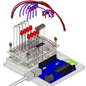
The board layout:

And my assembled version:

I’ve modified the original code provided by Ooolmout, but if you’d like to try that instead, it can be downloaded in full here. Explanation of the code is included, so copy and paste the whole thing from pastebin to read an explanation of the code.
Bit-Shifting (OutputBytes Function)
In the first loop example - outputBytes() - the code utilises a 8-bit sequence (a byte) which it then shifts left each iteration of the for loop. It’s important to note that if you shift further than is possible, the bit is simply lost.
Bit-shifting is done using << or >> followed by the number of bits you want to shift by.
Sending Integers Instead (OutputIntegers Function)
If you send a whole number to the shift register instead of a byte, it will simply convert the number into a binary byte sequence. In this function (uncomment in the loop and upload to see the effect), we have a for loop that counts from 0-255 (the highest integer we can represent with one byte), and sends that instead. It basically counts in binary, so the sequence may seem a little random unless your LEDs are laid out in a long line.
For example, if you read the binary explained article, you’ll know that the number 44 will be represented as 00101100, so LEDs 3,5,6 are going to light up at that point in the sequence.

Daisy Chaining More Than One Shift Register
The remarkable thing about Shift Registers is that if they are given more than 8-bits of information (or however large their registry is), they will shift the other additional bits out again. This means you can connect up a series of them together, push in one long chain of bits, and have it distributed to each register separately, all with no additional coding on your part.
Although we won’t be detailing the process or schematics here, if you have more than one shift register you can try the project from the official Arduino site here.
Other articles in the series:
- What Is Arduino & What Can You Do With It?
- What Is An Arduino Starter Kit & What Does It Contain?
- More Cool Components To Buy With Your Starter Kit
- Getting Started With Your Arduino Starter Kit ? Installing Drivers & Setting Up The Board & Port
- Fritzing, a free tool for drawing circuit diagrams
- A Closer Look At The Structure Of An Arduino App & The Example Blink Program
- Arduino Xmas tree lights project (AKA learning about arrays)
- What is Binary?
That’s as far as we’ll go with shift registers today, as I think we’ve covered a lot. As ever, I’d encourage you to play with and adjust the code, and feel free to ask any questions you may have in the comments, or even share a link to your awesome shift register based project.